Understanding Pumps & Compressors Integration Challenges in HVAC Systems
HVAC contractors in Singapore face unique challenges when integrating Pumps & Compressors into chilled water systems, heat pump circuits, and refrigerant loops. Unlike single-component failures, integration issues stem from mismatched flow rates, incompatible pressure ratings, or improper displacement sizing. Over 35 years serving industrial equipment needs across Asia-Pacific, 3G Electric has observed that 60% of system underperformance stems from poor component pairing rather than individual equipment failure.
When a chiller's compressor discharge pressure exceeds your pump's rated working pressure, or when pump displacement cannot maintain required flow velocity, the entire circuit degrades. This troubleshooting guide focuses on the comparative analysis needed to validate your system architecture before installation and diagnose integration problems after deployment.
Section 1: Pressure Compatibility and Rating Mismatches
The Core Integration Problem
Your Pumps & Compressors must operate within overlapping pressure envelopes. Many contractors overlook this fundamental requirement, selecting a high-capacity pump rated for 160 bar while pairing it with a compressor discharge line operating at 210 bar during peak load conditions. The result: accelerated seal wear, unexpected shutdown, and warranty disputes.
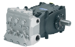
Consider two Pratissoli workhorses: the KF30 compact pump delivers 106 L/min at a 200 bar rated pressure with 40 kW input, while the MW40 industrial pump handles 211 L/min at 210 bar with 85 kW capacity. On paper, MW40 seems universally superior—but for a small modular chiller requiring 100 L/min at 160 bar sustained operation, the KF30 is the correct choice. The MW40's 210 bar rating means it's optimized for higher-pressure applications; forcing it into lower-pressure duty wastes energy and shortens bearing life.
Practical Comparison Framework
When evaluating pump-to-compressor pairing:
- Match discharge pressure: Compare your compressor's maximum discharge pressure (consult technical data sheets) against the pump's rated working pressure. A 20% safety margin is standard.
- Flow requirement alignment: Calculate your circuit's required flow in L/min (total system volume × circulation rate). The pump must meet or slightly exceed this figure without operating in the deep right-hand curve of its performance map.
- Displacement verification: For variable displacement pumps and compressors, ensure displacement ratings scale proportionally. A 100 cc/rev pump feeding a 50 cc/rev compressor creates pressure spikes during transient demand.
Interpump E1D1808 compact gear pump exemplifies a specialized integration solution: 8 L/min at 180 bar, 2.72 kW input. This unit suits oil-cooled compressor lubrication circuits or low-flow auxiliary cooling loops—but would be undersized as a primary chiller pump. The 180 bar rating perfectly matches many scroll compressor discharge lines found in modular HVAC equipment.
Section 2: Flow Rate Mismatch Diagnostics
Symptoms of Integration Flow Failures
When Pumps & Compressors operate at incompatible flow rates, several failure modes emerge:
- Insufficient pump displacement: Circuit velocity falls below 3 m/s in main lines, causing heat exchanger fouling and reduced thermal transfer. Temperature differential measurements will show abnormally high pressure-drop across the evaporator.
- Oversized pump capacity: The pump operates at the far left of its curve (very low flow), generating excessive heat and reducing volumetric efficiency. Compressor current draw increases as back-pressure rises.
- Transient flow shock: When a variable displacement pump tries to match a fixed-displacement compressor's demand, step changes in flow create pressure spikes that can rupture seals in downstream components.
Different compressor architectures require different pump strategies:
| Compressor Type | Typical Displacement | Pump Pairing Strategy | Integration Risk |
|---|---|---|---|
| Fixed-displacement rotary screw (50–100 cc/rev) | 50–100 cc/rev | Pump displacement = compressor displacement ±10% | Medium—requires accumulator for capacity modulation |
| Variable displacement swashplate (50–150 cc/rev) | Variable 0–150 cc/rev | Pump displacement = maximum compressor displacement | Low—load-sensing margin can absorb transient flow |
| Scroll compressor low-flow circuit | 10–30 cc/rev | Undersized pump (5–15 cc/rev) acceptable for oil cooling | Medium—verify pressure compensation active |
The Pratissoli SS71153 pump delivers 122 L/min at 160 bar with 37.5 kW motor input, making it ideal for mid-range fixed-displacement systems. Paired with a 60 cc/rev screw compressor (approximately 117 L/min at rated speed), this combination maintains velocity and efficiency across the operating envelope.
Diagnostic Test Procedure
If integration is suspected but not confirmed:
1. Measure pump outlet pressure and compare to compressor inlet. Pressure drop exceeding 5 bar indicates line restriction or internal pump wear.
2. Log pump case drain backpressure. If exceeding 3 bar, the pump's compensator is fighting excessive system pressure—sign of downstream blockage or incompatible relief setting.
3. Calculate actual flow: (system volume in liters ÷ fill time in minutes) × 60. Compare to pump nameplate displacement; deviation >15% suggests internal slippage or a misidentified pump model.
4. Monitor compressor current draw while varying pump speed (if VFD-driven). Current should decrease proportionally with speed; if current remains constant, the pump cannot respond to load changes—integration failure confirmed.
Section 3: Thermal Load Distribution and Component Sizing
Why Thermal Considerations Impact Integration
Pumps & Compressors generate heat proportional to their operating pressure and internal losses. In Singapore's tropical climate with ambient temperatures reaching 35°C, heat rejection becomes a critical integration variable. A pump sized for minimum displacement may overheat because it operates at high pressure differential; oversized displacement may underheat in winter chillers, allowing refrigerant to migrate during standby.
Comparing Thermal Profiles Across Product Families
The Interpump ET1C1612 SX*D20 pump (12 L/min, 160 bar, 3.68 kW) generates roughly 2.2 kW of continuous heat at 100% duty cycle in tropical ambient. In a confined plant room, this requires 8–10 liters/minute cooling circuit flow. Contrast with the MW40 (211 L/min, 85 kW): at full load, it dissipates 30–35 kW, demanding a separate cooler sized for 80+ liters/minute water circulation.
Integration failure occurs when:
- A compact pump (ET1C1612 class) is paired with an undersized cooler designed for smaller equipment
- A large pump (MW40 class) is installed in a system with cooler capacity sized for legacy equipment
- Variable displacement pumps are set to maximum stroke in steady-state operation, creating unnecessary heat that the original cooler cannot manage
- Calculate total system heat generation: (pump kW loss + compressor kW loss) × 0.85 rejection factor
- Size cooler capacity at 1.3× calculated heat load for 35°C ambient
- If cooler size is fixed, verify pump displacement can be reduced via load-sensing compensator without exceeding pressure relief setting
- Install thermostat bypass on cooler return; set differential to ±5°C from target (typically 45°C for chilled water systems)
- Log cooler outlet temperature weekly; rising trend indicates integration drift (fouling, reduced pump displacement, or compressor inefficiency)
Section 4: Practical Troubleshooting Decision Tree for Integration Issues
Step 1: Confirm System Baseline Parameters
Before diagnosing integration failure, establish what "normal" means for your system:
- Pump displacement and rated pressure (from nameplate or service manual)
- Compressor displacement, type (fixed or variable), and discharge pressure range
- System design flow rate (L/min) and design pressure (bar)
- Cooler capacity (kW) and target fluid temperature (°C)
- Record pump inlet pressure (should be 5–10 bar below atmospheric if pulling from reservoir)
- Record pump outlet pressure at full load
- Record compressor inlet pressure and discharge pressure
- Measure pump case drain backpressure and compressor case drain backpressure
- Calculate actual flow by timing system fill or using an inline turbine meter
| Issue | Expected Condition | Failure Indication | Root Cause |
|---|---|---|---|
| Low flow output | 100–110% of pump displacement | <85% of rated flow | Pump wear, internal leakage, or wrong pump model |
| High case drain pressure | 1–2 bar | >3 bar sustained | Cooler blockage, wrong oil type, or compensator malfunction |
| Rising discharge pressure | Stable at load setpoint | Climbing pressure despite constant load | Pump displacement drift, relief valve creep, or downstream restriction |
| Compressor starvation | Even pressure rise/fall across load cycle | Cyclical pressure collapse at compressor inlet | Pump undersized for compressor demand, or integration mismatch |
Step 4: Component-Level Diagnostics
If pump displacement is confirmed low:
- Drain oil and inspect for metallic particles (bearing wear)
- Remove pump and bench-test against a calibrated flow meter
- If bench flow recovers, the issue is system integration (cooler fouling, line blockage, or wrong relief pressure)
- If bench flow remains low, rebuild or replace pump
- Verify compressor displacement via manufacturer data; confirm it matches system nameplate
- Check cooler outlet temperature; if >55°C, insufficient cooling capacity
- Reduce pump displacement slightly (if variable) and observe whether compressor discharge pressure stabilizes
- If pressure remains high, compressor internal damage or wrong oil viscosity is likely (integration is secondary issue)
- Isolate pump case drain from compressor case drain; route pump drain directly to tank at atmospheric pressure
- If pump case pressure normalizes, the compressor's case drain is restricted (e.g., plugged crankcase heater) or your system uses incorrect pilot-operated relief sizing
- If pressure remains high, your pump's compensator is over-sensitive; adjust pilot ratio or install a case drain flow control orifice
Why HVAC Contractors Should Prioritize Integration Analysis
With 35+ years' experience supplying equipment to Singapore's industrial sector, 3G Electric emphasizes that integration troubleshooting saves time and cost compared to component replacement. A $500 diagnostic effort identifying a $50 relief valve adjustment is far superior to replacing a $5,000 pump that was never the problem.
For HVAC contractors, the investment in understanding how Pumps & Compressors interact—pressure compatibility, flow matching, and thermal distribution—translates directly to faster fault resolution, longer equipment life, and higher customer satisfaction scores.