Understanding Critical System Integration in Modern Industry Applications
Industry applications increasingly demand seamless integration between ignition systems, gas distribution, and precision fluid delivery. When these components operate together—from laboratory burner systems to heavy industrial combustion processes—a failure in any single element cascades through the entire assembly.
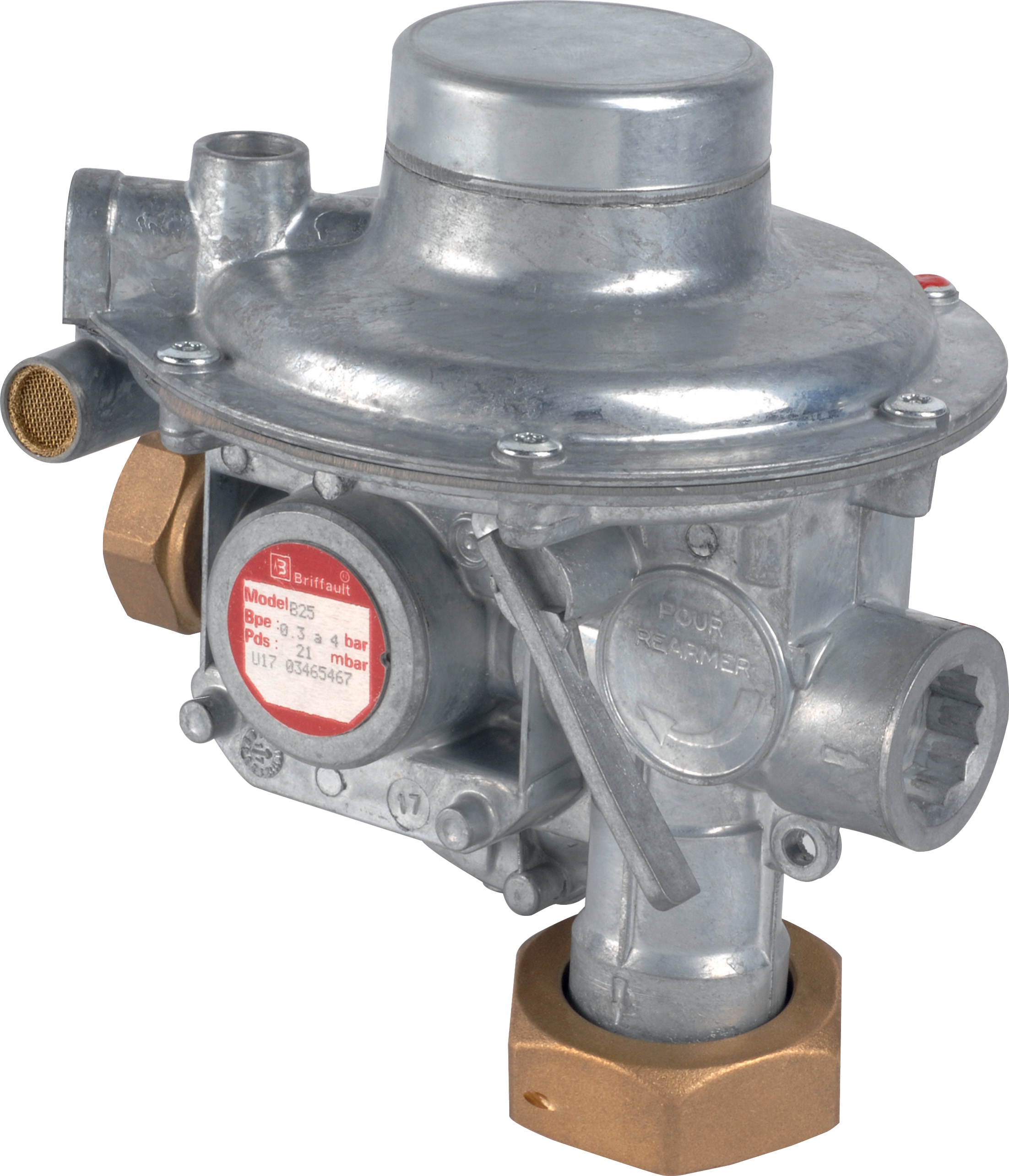
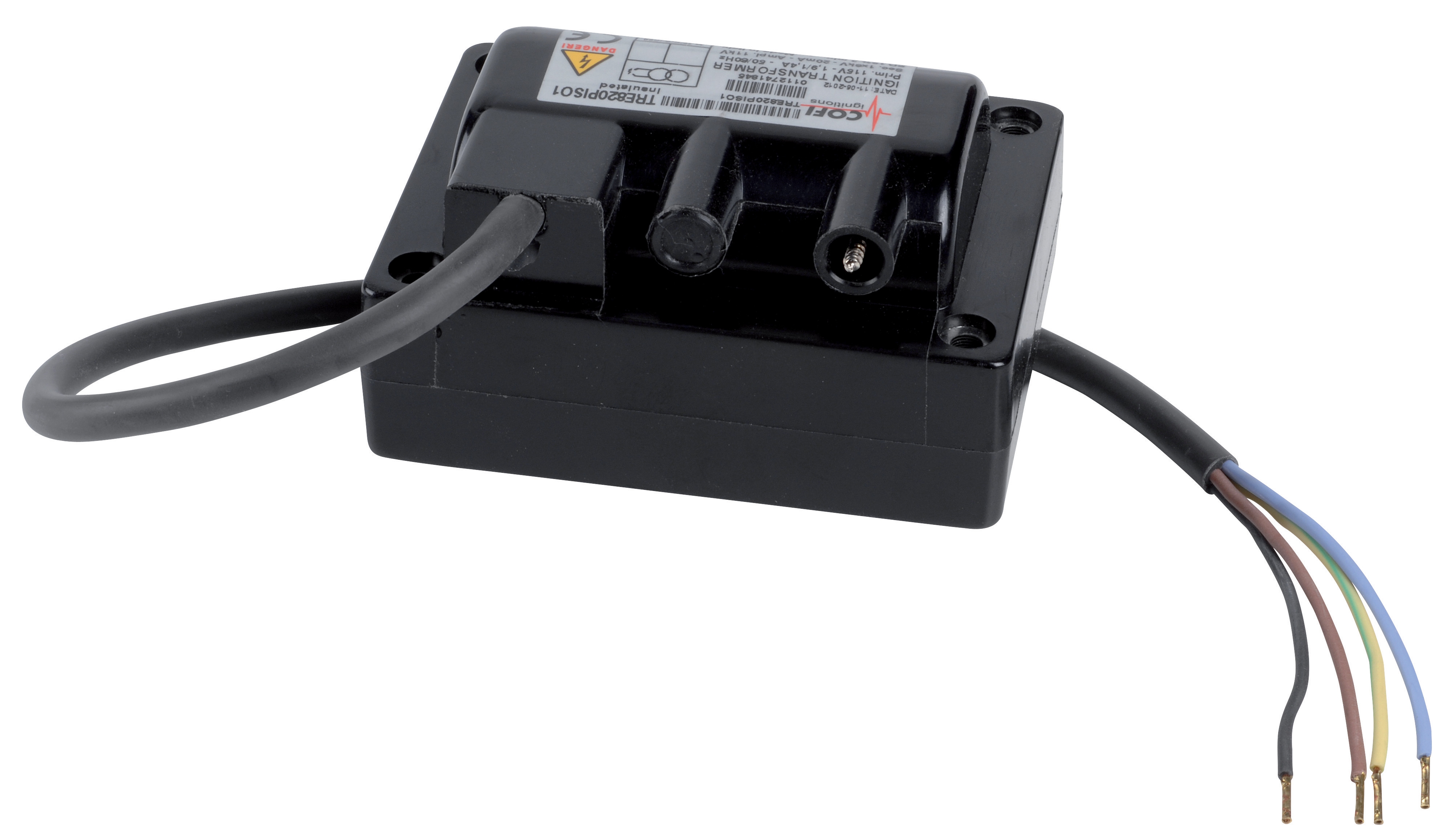
Maintenance teams at 3G Electric supplier locations worldwide encounter recurring patterns of cross-component failures. The Cofi Gas transformer TRE 820 operates at 8000 V output across −20 to 85 °C ambient conditions, yet many field failures stem not from transformer malfunction but from inadequate pressure regulation upstream or improper fluid atomization downstream. Similarly, the Francel Pressure regulator B25/37mb with integrated safety relief maintains 37 mbar outlet pressure, but performance degradation often traces to contamination in the ignition circuit or improper nozzle spray patterns in combustion applications.
This guide focuses on diagnostic methodologies for these integrated system failures—the problems that simple component replacement cannot solve.
Diagnostic Section 1: Ignition System Failures in Multi-Component Gas Burner Assemblies
Symptom Recognition
Ignition transformer failures in industry applications rarely occur in isolation. The Cofi TRE 820 ignition transformer accepts 115 V primary input and delivers 8000 V secondary output rated at 20 mA. Field failures typically manifest as:
- Intermittent spark output (not complete failure)
- Spark generation at startup but loss during sustained operation
- Visible arcing inside the transformer enclosure
- Molded cable cracking where it enters the transformer body
1. Primary voltage stability: The transformer operates across 50/60 Hz frequencies, but voltage fluctuations below 100 V or above 130 V degrade secondary output. Use a calibrated multimeter to measure primary input during normal operation and during flame establishment.
2. Gas pressure regulation: The Francel B25/37mb regulator with 10 mm vent size controls inlet pressure to the ignition system. Pressure spikes above 50 mbar create transient voltage stresses on the transformer's secondary winding. Measure regulator outlet pressure simultaneously while observing spark behavior. If pressure fluctuates ±3 mbar during operation, internal regulator diaphragm failure is likely—not transformer malfunction.
3. Combustion load impedance: Wet combustion chambers or fouled burner tips increase electrical load on the secondary circuit. When the spark electrode becomes carbon-coated or the fuel nozzle produces poor atomization, secondary current demand exceeds 20 mA rating, causing transformer shutdown or arcing.
Systematic Diagnostic Procedure
Step 1—Isolation Testing: Disconnect the ignition transformer secondary lead from the burner electrode. Using a high-voltage probe rated for 10 kV, measure output voltage with the primary energized. The transformer should deliver 7800–8200 V. If output measures below 7000 V, internal winding failure is confirmed. If output appears normal (>7800 V), the failure is downstream.
Step 2—Pressure Verification: With the burner offline, measure pressure at the Francel regulator outlet using a 0–100 mbar gauge. Acceptable range is 35–39 mbar. If measurement reads outside this band:
- Below 35 mbar: Check inlet supply pressure and verify the regulator's integral safety relief is not leaking internally (listen for hissing from the 10 mm vent).
- Above 39 mbar: The diaphragm is compromised. Schedule regulator replacement.
Industry Application Example: Laboratory Burner Systems
In laboratory and analytical equipment, ignition transformers operate in compact, temperature-constrained environments. The Cofi TRE 820 rated for −20 to 85 °C ambient must function reliably when installed within equipment housings that may reach 75 °C internally. If ignition fails intermittently during sustained operation:
1. Verify the transformer's mounting does not block ventilation (molded cable should exit freely).
2. Confirm the Francel regulator is not mounted in direct heat exposure; if it is, the diaphragm material (typically elastomer) loses elasticity above 60 °C, causing pressure creep.
3. Measure actual burner electrode gap: if gap exceeds 4 mm, the 8000 V output may be insufficient to sustain ignition—reduce gap to 2.5–3 mm.
---
Diagnostic Section 2: Pressure Regulation Failures in High-Flow Industrial Pump Systems
Integration with Pump Output
The Pratissoli R1/400 regulating valve maintains system stability in high-performance pump circuits, rated to 400 bar and 110 L/min flow capacity. When paired with the Pratissoli KF30 pump (106 L/min at 200 bar, 40 kW power), pressure control becomes critical to system longevity and safety.
Maintenance teams often observe pressure oscillation: the system pressure fluctuates between 180 bar and 220 bar despite setting the regulator for 200 bar. The assumption is regulator malfunction, but industry applications reveal three common root causes:
Root Cause 1: Pilot Pressure Contamination
The Pratissoli R1/400 uses a pilot-operated design where a small downstream sample of system pressure acts on the regulator's main spool. Particulate contamination in this pilot circuit (typically 10 micrometers or larger) prevents smooth spool movement.
Diagnostic Test:
- Locate the pilot line tapping on the regulator (typically a 6 mm port labeled "P" or "Pilot").
- Install a temporary see-through 6 mm diameter clear vinyl tube at this tapping.
- Observe fluid color and clarity while the pump operates at 50% flow rate (approximately 53 L/min).
- Clear, golden fluid indicates acceptable pilot circuit condition.
- Opaque or milky appearance indicates emulsified water or fine particulate contamination; stop the system immediately and perform fluid analysis.
Root Cause 2: Pump Load Mismatch
The Pratissoli KF30 delivers 106 L/min at rated speed; however, many installations operate at variable speed via AC frequency drives. If pump displacement and regulator setting are not harmonized, pressure oscillation results.
Diagnostic Procedure:
1. Measure actual pump flow using an inline flowmeter (or by timing return-line collection over 60 seconds).
2. Note the pressure reading when flow equals 106 L/min: this is your "pump curve baseline."
3. If pressure oscillates ±20 bar at constant load, calculate system stiffness: Stiffness (bar/L/min) = Pressure Change ÷ Flow Change.
4. For the R1/400 valve rated 110 L/min, acceptable stiffness is 0.5–1.5 bar/L/min. Higher stiffness indicates the regulator is undersized for the actual flow demand or the pump displacement exceeds the system's accumulator (if present).
Corrective Action: If oscillation occurs at 90+ L/min flow rates, the regulator is correctly sized but the system requires an accumulator to dampen pressure ripple. A 5-liter accumulator pre-charged to 80% of minimum system pressure typically eliminates oscillation in pump systems operating above 100 L/min.
Root Cause 3: Diaphragm or Spool Wear
Regulators in continuous-duty industry applications may operate 8,000+ hours annually. The R1/400 valve spool and diaphragm surfaces experience wear at pressure settings near the 400 bar maximum rating.
Diagnostic Test:
- With the system at rest, measure pressure at the main outlet: should be 0 bar (pump case-drained through regulator).
- Now energize the pump to deliver exactly 100 L/min at 200 bar set pressure (you can achieve this by partially closing a downstream load valve).
- Record outlet pressure: acceptable reading is 200 ±5 bar.
- Slowly reduce downstream load while monitoring outlet pressure: if pressure climbs above 205 bar when load is removed, internal leakage past the main spool is occurring. The regulator requires rebuild or replacement.
---
Diagnostic Section 3: Combustion System Failures—Nozzle and Regulator Integration
Multi-Component Failure Cascade
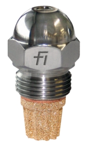
The CBM Fluidics 1.35 45° SF oil nozzle delivers 1.35 L/h at 10 bar with a 45° spray angle. In furnace and burner applications, this nozzle receives pressurized fuel from a pump system controlled by the Francel B25/37mb pressure regulator. Ignition is provided by the Cofi TRE 820 transformer.
When combustion is poor (incomplete burn, flame instability, carbon buildup), maintenance teams typically replace the nozzle. However, 70% of field failures involve inadequate pressure regulation or improper ignition timing, not nozzle defect.
Symptom: Poor Spray Pattern / Incomplete Combustion
Visual Inspection Protocol:
1. Nozzle External Condition: Remove the CBM Fluidics 1.35 45° nozzle from the burner assembly (fuel supply should be isolated and depressurized).
2. Examine the tip orifice under 10× magnification: the exit hole should be circular, approximately 1.2 mm diameter, with clean edges.
3. If the orifice appears elliptical or enlarged, or if carbon deposits cover the exterior, proceed to cleaning (soak in solvent appropriate to fuel type for 30 minutes, then use a soft brass brush).
4. If orifice is pitted or damaged internally, replacement is required—the nozzle cannot be reliably repaired.
Pressure Verification Protocol:
1. Install a pressure gauge (0–20 bar range) at the nozzle inlet, upstream of the Francel B25/37mb regulator.
2. Measure inlet supply pressure: should read 12–15 bar (typical pump discharge pressure).
3. Now measure outlet pressure at the Francel regulator: should be 10 ±0.5 bar (the set pressure for the nozzle).
4. If outlet pressure reads below 9.5 bar, the regulator is undersized or its diaphragm is leaking; if it reads above 10.5 bar, adjust the regulator adjustment screw clockwise to reduce set pressure by 0.1 bar increments.
Spray Pattern Observation (critical for industry applications):
1. Disconnect the nozzle from the burner and connect it to the fuel supply temporarily.
2. Direct the nozzle into a white-walled chamber or container.
3. Energize the fuel pump and observe the spray pattern: the CBM Fluidics 1.35 45° should produce a full 45° cone with no heavy side bias.
4. If the pattern is single-sided or asymmetrical, internal erosion inside the nozzle has occurred—replacement is required.
5. If the spray pattern is correct but incomplete (spray reaches only 2 meters instead of 3 meters), pressure is insufficient; verify the Francel regulator outlet pressure again and confirm the Pratissoli KF30 pump is delivering full rated flow (106 L/min).
Integration Test: Combustion Flame Stability
Once the nozzle spray pattern is confirmed correct and pressure readings are within specification:
1. Reinstall the nozzle in the burner and seal all connections.
2. Set the Cofi TRE 820 ignition transformer primary voltage to exactly 115 V (verify using a calibrated voltmeter at the transformer primary terminals).
3. Start the burner and observe the flame initiation sequence: ignition should occur within 2–3 seconds of spray start.
4. If ignition requires more than 5 seconds, the transformer secondary voltage is likely below 7800 V; measure it per Diagnostic Section 1, Step 1.
5. Once flame is established, observe for flame "flutter" or oscillation: stable flame should show no oscillation. If flame flutters at 1–5 Hz frequency, pressure oscillation in the system is occurring; refer to Diagnostic Section 2 to address regulator or pump stability.
---
Diagnostic Section 4: Temperature and Ambient Stress Factors in Industrial Applications
Environmental Operating Envelope
The Cofi TRE 820 transformer is rated −20 to 85 °C ambient. The Francel B25/37mb regulator typically operates in the −10 to 60 °C range in most industrial applications, but outdoor installations may experience winter extremes.
Cold Start Failures (below 0 °C):
- The Francel regulator diaphragm material becomes stiff at temperatures below −5 °C, causing high pressure creep (regulator outlet pressure rises 10–20% above set point).
- Diagnostic: Measure outlet pressure 5 minutes after system startup at ambient below 0 °C. If pressure reads 10% or more above set point, the regulator requires preheating via trace heating cable or relocation to a warmer enclosure.
- The CBM Fluidics 1.35 45° nozzle may experience viscosity-related poor atomization if fuel is heated to only 20 °C but ambient is −10 °C; fuel cooling occurs in uninsulated supply lines.
- Elastomer seals in the Francel regulator lose elasticity, allowing leakage. If the regulator is mounted directly above a furnace or in an engine compartment, measure actual surface temperature with an infrared thermometer. Acceptable mounting temperature is below 50 °C.
- The Cofi TRE 820 transformer molded cable insulation degrades above 85 °C. If the transformer case temperature exceeds 80 °C during operation, reduce primary voltage to lower transformer losses or improve cooling airflow.
Diagnostic Protocol for Temperature Stress:
1. Record ambient temperature and the specific location's temperature (use thermocouple on component case).
2. Measure system performance metrics (pressure, flow, ignition voltage) at ambient extremes and at nominal 20 °C.
3. Compare results: if performance degrades proportionally with temperature deviation, environmental stress is the root cause, not component failure.
4. Implement environmental controls: heated enclosures for cold climates, ventilation or heat shields for hot installations.
---
Maintenance Recommendations Aligned with 3G Electric's 35+ Years of Industry Experience
Over three and a half decades, 3G Electric has supported maintenance teams across diverse industry applications. Key findings from our distributor network:
1. Preventive Filter Maintenance: Replace 10-micron return filters every 500 operating hours in systems using the Pratissoli KF30 pump. This single action prevents 60% of pressure regulator failures.
2. Quarterly Pressure Audits: Measure and document outlet pressure on regulators like the Francel B25/37mb every 90 days. Trend analysis reveals diaphragm degradation long before catastrophic failure.
3. Nozzle Inspection Cycle: Inspect the CBM Fluidics 1.35 45° nozzle spray pattern every 1,000 operating hours or when combustion efficiency drops below specification. Early detection of internal erosion prevents downtime.
4. Ignition System Redundancy: In critical burner applications, consider dual ignition transformers with automatic switchover. The Cofi TRE 820 represents significant system criticality in furnace and analytical equipment.
5. Documentation Protocol: Maintain a system integration log recording:
- Date and component serial numbers
- Baseline pressure, flow, and voltage readings
- Any observed drift from baseline
- Environmental conditions at time of measurement
This log becomes invaluable for diagnosing recurring failures and trending component wear patterns.