Understanding Controls & Safety in Modern HVAC Burner Systems
Controls & Safety represent the operational backbone of industrial HVAC burner installations. For HVAC contractors, the stakes are high: improper valve selection or relay integration can result in system inefficiency, safety violations, and costly callbacks. Drawing on 35+ years of experience distributing industrial equipment globally, 3G Electric recognizes that Controls & Safety decisions directly impact both system reliability and regulatory compliance across different geographic markets.
The core challenge lies in matching component response characteristics to specific burner operating conditions. HVAC systems operate under varying pressure conditions, fuel types, and safety requirements. A solenoid valve optimized for one application may perform inadequately or dangerously in another. Similarly, relay selection affects response timing, diagnostic capabilities, and integration with flame detection systems. This article provides contractors with a practical framework for evaluating Controls & Safety components that balance safety, efficiency, and installation flexibility.
Fast-Response vs. Slow-Response Solenoid Valves: When to Deploy Each
Solenoid valves represent the most critical single control element in any HVAC burner system. Response speed—measured in milliseconds—determines how quickly gas supply can be interrupted during fault conditions or normal burner cycling. The distinction between fast and slow solenoid valves is not merely academic; it affects system safety margins, equipment wear, and compliance with regional safety standards.
Fast-Response Solenoid Valve Applications
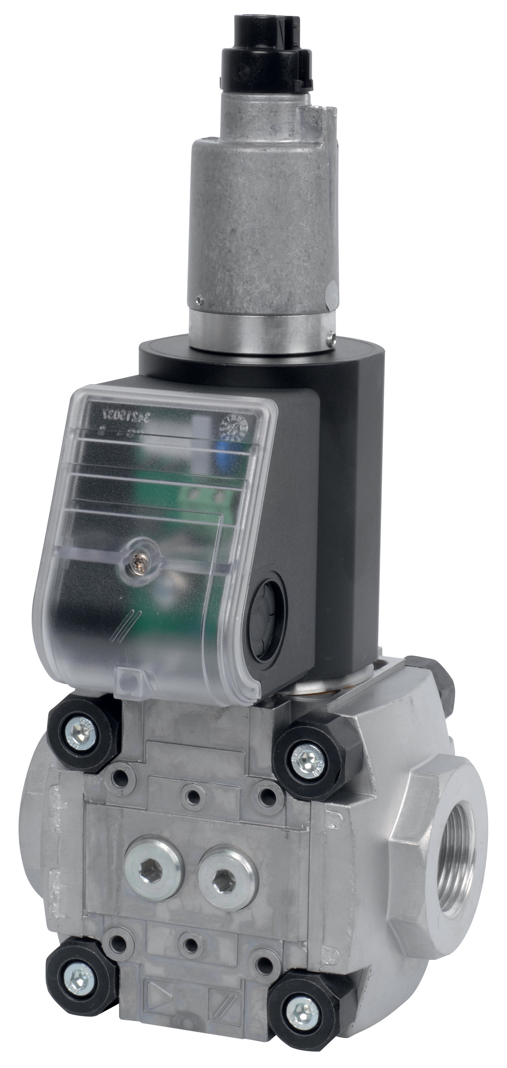
The CBM Fast gas solenoid valve VAS 110R/NW and CBM Fast gas EV VAS 365R/NW are engineered for rapid gas cutoff in safety-critical scenarios. Fast-response valves typically actuate within 50-150 milliseconds, making them ideal for:
- Flame detection integration: When burner flame extinguishes unexpectedly, fast-response valves must interrupt gas supply before the combustion chamber fills with unburned fuel. This prevents dangerous flare-ups and satisfies stringent safety requirements in North America, Europe, and Asia-Pacific regions.
- High-pressure applications: Larger burner capacities and higher operating pressures demand faster valve response to maintain proportional control. The VAS 365R/NW, with its expanded orifice size, provides both rapid response and higher flow capacity—essential for industrial-scale HVAC systems.
- Modulating burner systems: Systems requiring continuous flow adjustment during operation benefit from fast-response characteristics that enable precise fuel-air ratio control.
For contractors installing safety-critical systems or working under strict compliance frameworks (such as EN 676 in Europe or ANSI Z21.13 in North America), fast-response valves provide the margin of safety required.
Slow-Response Solenoid Valve Applications
The CBM Slow gas solenoid VAS 125R/LW and CBM Slow gas solenoid valve VAS 340R/LW serve different operational needs. Slower response times (250-400 milliseconds) are appropriate when:
- Pressure transient protection is required: Fast-acting valves in certain system configurations can create water-hammer effects or pressure spikes that damage downstream components. Slow-response valves manage these transients by easing gas supply transitions.
- Pilot light support systems operate independently: Traditional pilot-ignition burners with dedicated pilot fuel supplies can tolerate slower main valve response because the pilot light remains stable during transitions.
- Installation involves longer fuel supply lines: In retrofit situations where burner distance from gas supply exceeds 20 meters, slow-response valves accommodate the hydraulic lag inherent to extended piping.
- Cost-conscious applications prioritize reliability over maximum control speed: Slow-response valves offer proven long-term durability and lower replacement costs, beneficial for budget-constrained facilities managing large burner populations.
The VAS 340R/LW's larger displacement capacity combined with moderated response speed makes it ideal for institutional facilities—schools, hospitals, large office buildings—where burner cycling is predictable and equipment lifespan expectations are high.
Relay Integration: From Simple On-Off Control to Diagnostic Safety Systems
Solenoid valves require control signals from safety relays—electrically activated switches that manage valve opening and closing sequences. This seemingly simple interface masks significant complexity: relay selection affects diagnostic capabilities, integration with flame detection, and compliance with fail-safe standards.
The CBM Relay DMG 970-N MOD.03 represents modern relay architecture optimized for HVAC burner safety applications. This relay functions beyond simple on-off switching:
Core Relay Functions
- Flame monitoring integration: The DMG 970-N MOD.03 accepts flame detection signals (typically from infrared flame sensors or photo-resistive cells) and continuously validates flame presence during operation. If flame signal drops below acceptable thresholds, the relay de-energizes solenoid valves, cutting fuel supply within milliseconds.
- Ignition sequence management: Relays orchestrate burner startup procedures—energizing ignition spark, allowing fuel valve opening, waiting for flame confirmation, then transitioning to full firing. Each sequence step is timed; deviation triggers shutdown.
- Diagnostic memory: Modern relays store fault codes identifying specific failure modes: flame loss, ignition failure, safety switch activation, fuel pressure anomalies. This diagnostic capability accelerates troubleshooting and reduces callback time.
Contractors must coordinate relay response timing with solenoid valve speed characteristics. Consider this practical scenario:
A retrofit installation replaces an aging burner in a hospital boiler room. The existing piping runs 15 meters from the gas meter to the burner control valve, with two 90-degree bends and a pressure regulator. A fast-response solenoid valve (VAS 110R/NW) paired with an aggressive relay (minimum 100ms de-energization delay) could create pressure transients that trigger the facility's main gas shutoff. Solution: specify the slow-response VAS 125R/LW instead, allowing pressure adjustments to stabilize before the relay initiates its next control cycle. This eliminates nuisance shutdowns while maintaining all safety functionality.
The DMG 970-N MOD.03 relay's configurable timing parameters accommodate such installation-specific requirements, enabling contractors to optimize the solenoid-relay pairing for each facility's unique piping configuration and pressure profile.
Practical Selection Framework for Global HVAC Installations
With 35+ years of experience supporting contractors across diverse markets, 3G Electric has identified decision criteria that transcend regional variations:
Step 1: Determine Burner Capacity and Fuel Type
Flow rate requirements establish baseline valve selection. Small commercial installations (under 500 kW thermal output) typically operate effectively with the VAS 125R/LW or VAS 110R/NW. Larger facilities and industrial applications benefit from the expanded capacity of the VAS 340R/LW or VAS 365R/NW. Confirm fuel type (natural gas or propane) and supply pressure; regulatory bodies sometimes mandate specific valve types based on these factors.
Step 2: Identify Safety Standard Compliance Requirements
Geographic location determines applicable standards:
- Europe: EN 676 (Gas burners), EN 61326-1 (Electrical safety). These standards typically require dual solenoid valve configurations with fast response times. The VAS 110R/NW or VAS 365R/NW satisfy these requirements.
- North America: ANSI Z21.13 (Safety Interlocks for Gas Appliances), CSA B149.2 (Gas Installation Code). Regional variations exist; consult local authority having jurisdiction (AHJ).
- Asia-Pacific: Standards vary significantly. Singapore follows equivalent European standards; Australia references AS/NZS 3000. Contractors must verify local regulations before component selection.
When in doubt, default to fast-response valve specifications with modern relay controls like the DMG 970-N MOD.03. This conservative approach satisfies most jurisdictional requirements and provides maximum safety margin.
Step 3: Assess Existing System Infrastructure
Retrofit installations constrain options. If replacing a failed component in an operational system:
- Measure actual fuel supply pressure at the control valve inlet
- Determine piping run distance from meter to burner
- Identify any pressure transient history (previous water-hammer events, nuisance shutdowns)
- Consult the existing burner control documentation to understand relay sequencing expectations
This intelligence informs whether to maintain the original valve type (preferred for compatibility) or upgrade to improved components. If upgrading, the relay (DMG 970-N MOD.03) can be independently optimized without necessarily changing the solenoid valve.
Step 4: Consider Long-Term Maintenance and Parts Availability
Solenoid valve coils and seals require periodic replacement. 3G Electric's 35+ year distribution history ensures that CBM components maintain parts availability across geographic markets. When contractors specify standard CBM solenoid valves and relays, they protect customers against future obsolescence and guarantee maintenance support for system lifespan.
Conclusion: Balancing Safety, Efficiency, and Contractor Flexibility
Controls & Safety component selection requires matching technical specifications to application requirements while respecting regulatory constraints and installation realities. Fast-response solenoid valves (VAS 110R/NW and VAS 365R/NW) excel in safety-critical applications demanding rapid response. Slow-response alternatives (VAS 125R/LW and VAS 340R/LW) provide proven reliability in stable, well-documented installations.
The relay—particularly the DMG 970-N MOD.03—determines how effectively solenoid valve performance translates into system safety. Modern relays integrate flame detection, diagnostic reporting, and configurable sequencing that older controls cannot match.
For HVAC contractors managing diverse installations across regions with varying standards, 3G Electric's curated component portfolio provides the flexibility to optimize Controls & Safety for each application while maintaining compatibility, regulatory compliance, and long-term support.