Understanding Controls & Safety in Emergency Shutdown Design
Controls & Safety systems form the backbone of industrial risk management, yet many procurement engineers approach them reactively rather than strategically. Drawing on 35+ years of experience distributing industrial equipment globally, 3G Electric recognizes that effective emergency shutdown architecture begins during the specification phase—not after an incident occurs.
Emergency shutdown (ESD) systems must accomplish three critical objectives: detect hazardous conditions rapidly, execute controlled shutdown sequences reliably, and provide auditable records of all events. This requires integration across multiple layers: detection sensors, logic controllers, solenoid valves, relays, and final control elements. Each component must meet specific safety integrity levels (SIL) appropriate to your application.
The stakes are high. A failed solenoid valve during emergency gas isolation can transform a manageable situation into a catastrophic event. A relay that fails to de-energize can prevent proper shutdown sequence execution. These aren't theoretical concerns—they're daily operational realities that procurement engineers must address through careful specification.
Section 1: Risk Assessment and SIL Determination
Before specifying any Controls & Safety component, conduct a systematic risk assessment that drives your safety integrity level requirements. This assessment should:
- Identify hazardous events specific to your process (gas leaks, pressure excursions, flame loss, temperature runaway)
- Determine consequence severity using industry standards (ISO 13849-1, IEC 61508) with clear definitions for Minor, Major, Serious, and Catastrophic outcomes
- Estimate event probability based on historical data and failure mode analysis
- Calculate risk by combining severity and probability
- Specify required SIL (1-4 scale, where 4 represents the highest safety requirement)
This process isn't bureaucratic overhead—it directly determines which products you can specify. A SIL 2 solenoid valve cannot be used for SIL 3 applications, creating procurement complications and compliance violations.
For gas isolation applications, most facilities require SIL 2 minimum. Industrial burner systems with dual fuel capability typically demand SIL 2 or SIL 3. Process equipment controlling hazardous chemical reactions often requires SIL 3 or SIL 4.
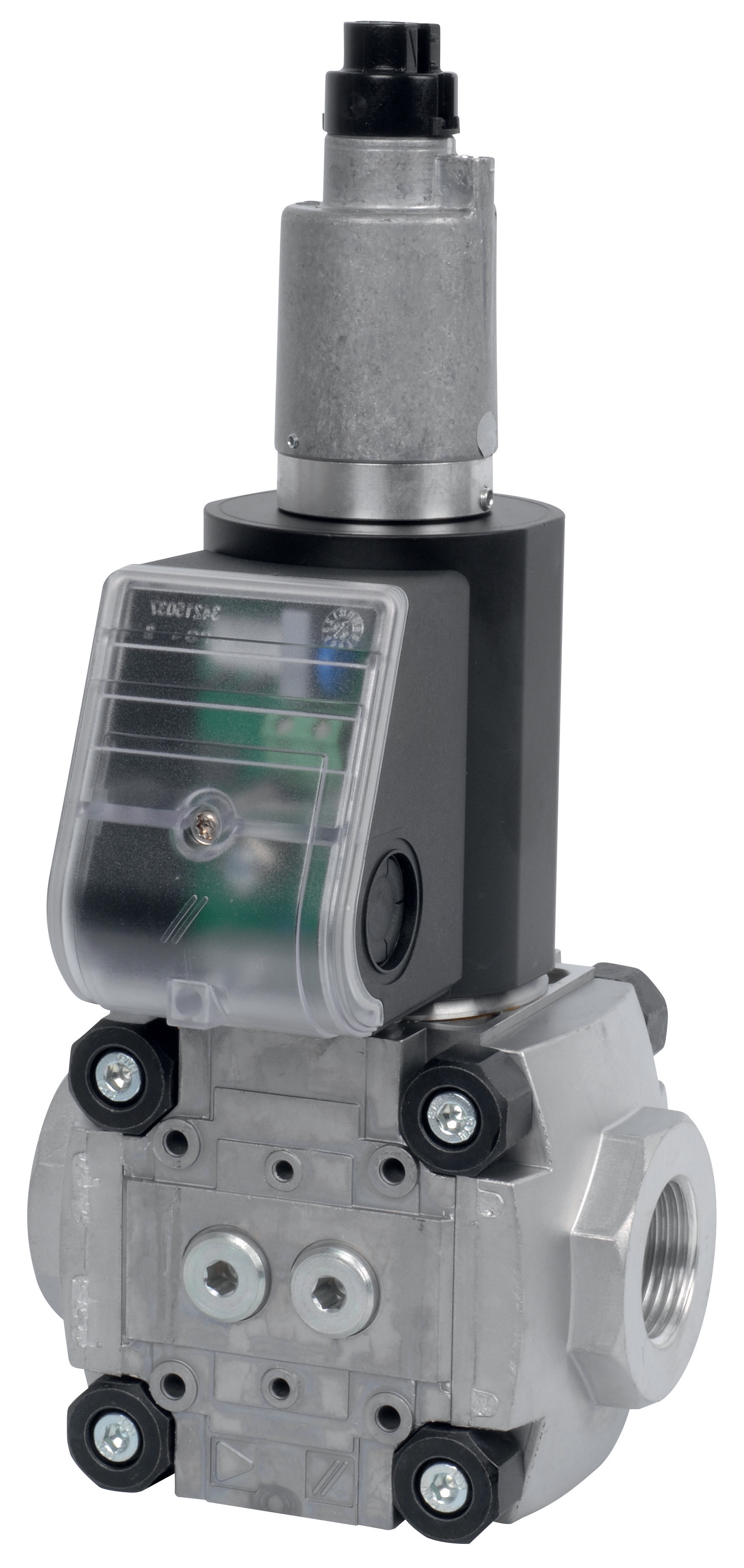
Once you've established SIL requirements, document them formally. This becomes your specification baseline and justifies your component selections to auditors and regulatory bodies. When sourcing solenoid valves like CBM Slow gas solenoid valve VAS 340R/LW or CBM Slow gas solenoid VAS 125R/LW, confirm each component's certified SIL rating and obtain documentation from your supplier.
Section 2: Designing Redundancy and Diversity in Shutdown Circuits
Controls & Safety philosophy demands that no single failure can prevent shutdown. This principle drives architecture decisions that many procurement engineers approach incorrectly.
Redundancy means having multiple pathways to accomplish shutdown. For example, gas isolation might employ two solenoid valves in series: a fast-acting valve like CBM Fast gas solenoid valve VAS 110R/NW for rapid response, plus a slower block valve CBM Slow gas solenoid valve VAS 340R/LW for positive isolation. If the fast valve fails to close, the block valve still provides isolation. If the block valve fails, the fast valve maintains protection.
Diversity means using different technologies or manufacturers for critical redundant functions. Relying on two identical solenoid valves from the same production batch creates common-mode failure risk—a manufacturing defect could disable both simultaneously. Better practice: specify fast gas valves with solenoid actuation plus manual block valves as diversity, or employ different valve technologies entirely.
When specifying control relays for shutdown circuits, the CBM Relay DMG 970-N MOD.03 provides proven performance in safety-critical applications. However, don't specify identical relays for all functions. Use different relay models for independent shutdown pathways to ensure diversity.
Practical implementation checklist:
- Design shutdown architecture with at least two independent pathways to safe state
- Specify components from different manufacturers or production families when possible
- Require proof-testing intervals to detect hidden failures before they impact safety
- Document the failure mode and effects analysis (FMEA) showing how redundancy addresses each identified failure
- Establish maintenance procedures distinguishing between channels to prevent common-mode maintenance errors
Section 3: Specification, Testing, and Procurement Strategy
Your Controls & Safety specification must balance technical rigor with procurement practicality. Here's how to structure effective specifications:
Create a Controls & Safety specification matrix listing each safety function (gas isolation, ignition shutdown, flame loss response), its required SIL, redundancy approach, component types, and testing requirements. This becomes your procurement roadmap.
When sourcing solenoid valves, specify both electrical and functional performance:
- Electrical: voltage, coil type, response time under rated load
- Functional: flow capacity under system pressure, leakage limits, seat material compatibility
- Safety: SIL rating with supporting documentation, certification standards met, proof-test intervals
- Environmental: operating temperature range, vibration tolerance, corrosion resistance
For CBM Fast gas EV VAS 365R/NW, verify that its fast response time (typically <100ms) meets your shutdown sequence timing requirements. Slower valves like the VAS 340R/LW series serve block functions where speed is less critical but isolation integrity is paramount.
Critical procurement decisions:
1. Source from distributors - 3G Electric's 35+ years in industrial equipment distribution means we maintain full technical documentation, traceability records, and genuine warranty support. Counterfeit solenoid valves and relays represent a genuine risk in global procurement.
2. Require pre-commissioning validation - Don't accept components without functional testing documentation. For solenoid valves, verify response time under your actual system pressure. For relays, test contact ratings and dropout voltages in your circuit configuration.
3. Plan proof-testing intervals - SIL-rated components require periodic functional testing (typically every 1-3 years depending on SIL level). Build this into your maintenance budgets and spare parts inventory.
4. Document everything - Maintain records of all Controls & Safety component specifications, test results, and maintenance. This documentation justifies your risk assessment and demonstrates due diligence if incidents occur.
Section 4: Installation, Commissioning, and Validation
Where most Controls & Safety programs fail is in the transition from specification to operation. A perfectly specified system can fail if installation and commissioning don't validate the design.
Pre-installation verification:
- Confirm all components match specification documents exactly (model numbers, SIL ratings, certifications)
- Verify component certificates of conformance and testing reports
- Inspect for physical damage during shipment—any dents or corrosion on solenoid valve bodies require rejection
- Test all electrical components (relays, solenoids) with megohmmeter before installation to confirm proper insulation
- Install solenoid valves with proper orientation and support to prevent mechanical stress
- For dual solenoid redundancy, mount them independently to prevent common vibration transmission
- Wire control circuits to allow testing of each redundant channel independently
- Use color-coded or labeled wiring for all shutdown circuits to prevent maintenance errors
- Install isolation block valves near solenoid valves to enable maintenance without depressurizing entire systems
1. Functional testing - Manually energize each solenoid valve and relay independently; confirm proper actuation and de-actuation
2. Timing validation - Measure actual response times under operating pressure and temperature; compare to specifications
3. Redundancy verification - De-energize each channel individually and confirm the parallel channel maintains control function
4. Proof-test documentation - Perform full proof-test as-built and document baseline performance for future comparison
5. Personnel training - Ensure all operators understand shutdown sequence, manual override procedures, and emergency protocols
After commissioning, establish a quarterly proof-testing schedule where you physically actuate each shutdown component and verify response. Document results. This proves to regulators and auditors that your Controls & Safety systems remain functional.
Integrating Controls & Safety Into Procurement Workflow
Effective Controls & Safety procurement isn't a one-time event—it's a continuous process improvement cycle. After each shutdown event (even partial or test-triggered), analyze what worked and what didn't. Update your specifications accordingly.
Work with distributors like 3G Electric who understand safety-critical applications. We've supported industrial operations globally since 1990, maintaining relationships with manufacturers who provide full technical support, rapid replacement capability, and honest guidance about component limitations.
When you encounter a new application type, don't assume your previous specifications apply. Conduct fresh risk assessment. Process conditions change, regulations evolve, and new technologies emerge. Your Controls & Safety program should reflect current best practices, not historical decisions.
The investment in rigorous Controls & Safety specification and validation prevents far more costly outcomes than any component ever will.