Introduction: Why Controls & Safety Maintenance Matters
Controls & Safety systems are the backbone of reliable industrial operations, yet they often receive maintenance attention only when failure occurs. For maintenance teams managing complex burner installations, pilot lights, solenoid valves, and relay systems, a structured preventive maintenance approach is essential.
At 3G Electric, with over 35 years of experience distributing industrial equipment globally, we've seen how proper Controls & Safety maintenance prevents costly shutdowns and keeps operations running safely. This guide provides practical, actionable procedures your team can implement immediately to maintain critical safety components.
Section 1: Understanding Your Controls & Safety System Components
Before you can maintain your system effectively, you need to understand what you're maintaining. A typical industrial Controls & Safety system includes three critical component types:
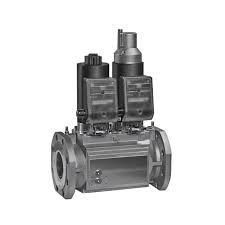
Solenoid Valves control gas flow and respond to safety signals. The CBM VCS 1E25R/25R05NNWL3/PPPP/PPPP double solenoid valve is a common industrial example that manages gas supply to your burner. When you understand that this valve contains internal windings and moving plungers, you'll recognize why debris and moisture damage them.
Relays act as electrical intermediaries, amplifying weak signals to control larger electrical loads. The CBM Relay CM391.2 30.5 1.2 coordinates electrical signals between your control system and safety devices. Relays contain electromagnetic coils and mechanical contacts that wear over time.
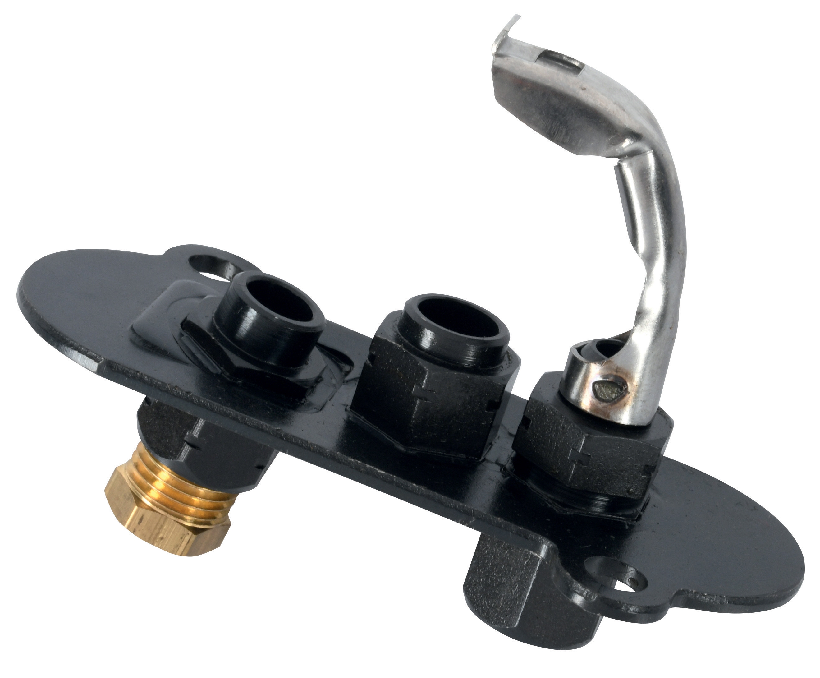
Pilot Lights provide visual confirmation of system status and serve as backup flame sources. Both the CBM 1-flame pilot light 0.150.082 and CBM Pilot light 1 flame 0140026 require clean gas supplies and proper electrode maintenance.
Bases and Mounting Systems like the CBM Base LGK AGM17 provide secure installation and proper electrical contacts. A loose or corroded base can cause intermittent failures that are difficult to diagnose.
Understanding these components helps your team recognize failure patterns and address root causes rather than just replacing failed parts.
Section 2: Preventive Maintenance Procedures for Solenoid Valves
Solenoid valves fail for predictable reasons. Implementing a preventive maintenance schedule dramatically improves reliability.
Visual Inspection (Monthly)
Start with basic visual checks:
- Inspect the valve body and coil housing for corrosion, especially if your system operates in humid or coastal environments
- Check for visible mineral deposits or discoloration on the valve body, indicating internal scaling from hard water or contaminated gas
- Verify that all cable connections are tight and that insulation shows no signs of cracking or damage
- Look for small oil or gas leaks around the valve seal areas
- Confirm the coil is firmly seated and shows no loose windings or exposed copper
If you notice corrosion or loose connections at this stage, address them immediately.
Electrical Testing (Quarterly)
Solenoid coils degrade electrically before they fail mechanically:
- Use a multimeter to measure the coil resistance. Record this baseline value on installation
- Compare current readings to your baseline—a significant increase (more than 20%) indicates insulation degradation
- Test for continuity between the coil terminals and the valve body. Any continuity suggests moisture has compromised the insulation
- If your system uses the CBM VCS 1E25R/25R05NNWL3/PPPP/PPPP double solenoid valve, test each solenoid independently to identify which circuit is failing
Electrical testing catches failures 2-4 weeks before the valve actually stops functioning, giving you time to plan replacement.
Gas Supply Quality (Semi-Annually)
Dirty or moist gas is the leading cause of solenoid valve failure:
- Check your gas supply filters and strainers. Clean or replace them if you see debris accumulation
- Install a moisture trap upstream of your solenoid valves if one doesn't exist. Gas containing moisture will deposit minerals inside the valve spool
- Test gas pressure to ensure it matches the valve's rated operating range. Pressure spikes can damage internal seals
- If you've experienced repeated solenoid failures, consider installing a gas dryer or running a test cycle with cleaned gas to verify the gas supply is the problem
Verify that your solenoid actually moves the internal spool:
- With the system de-energized, manually apply gas pressure and listen carefully for a clicking sound when you energize the coil. Silence indicates the solenoid plunger isn't moving
- If the solenoid is unresponsive, try briefly increasing the supply voltage by 10% to see if the plunger engages. If it does, electrical supply voltage is too low for reliable operation
- For dual-solenoid systems like the CBM VCS 1E25R/25R05NNWL3/PPPP/PPPP double solenoid valve, test each solenoid separately to isolate which one is failing
Section 3: Relay and Control System Maintenance
Relays are simple devices with few moving parts, but they fail in ways that create subtle system problems.
Contact Cleaning (Semi-Annually)
Relay contacts become corroded and cause intermittent operation:
- De-energize the relay completely before working on it
- For the CBM Relay CM391.2 30.5 1.2, remove the cover carefully to expose the internal contacts
- Inspect contacts for discoloration, pitting, or black carbonized deposits. Clean discoloration indicates oxidation; pitting means the contacts are reaching end-of-life
- Use fine-grit sandpaper (400-600 grit) to gently smooth contact surfaces. Wipe away all dust with a dry, lint-free cloth
- Never use liquid solvents, which can leave residue that prevents proper electrical contact
- If contacts are severely pitted or damaged, replacement is more cost-effective than cleaning
Relay coils fail silently:
- Measure coil resistance with a multimeter. Compare to the manufacturer's specification (typically 300-600 ohms for industrial relays)
- Resistance significantly higher than spec indicates coil degradation; lower resistance suggests internal short
- Test the relay's pull-in voltage by slowly increasing supply voltage until the relay clicks and engages. It should engage reliably at 75-85% of rated voltage
- Record this value monthly. Creeping increases in required voltage indicate coil degradation
The CBM Base LGK AGM17 and other relay bases are critical for proper operation:
- Inspect the base for cracks or loose pins
- Test for corrosion on the pins and sockets. Clean lightly with sandpaper if needed
- Verify the relay seats firmly in the base with no rocking or movement
- Apply a small amount of dielectric grease to the pins to prevent corrosion and ensure reliable contact
- If a base shows visible corrosion or cracks, replace it immediately—poor contact will cause intermittent failures throughout your system
Section 4: Pilot Light System Maintenance
Pilot lights are simple but essential components that require regular attention.
Electrode Cleaning (Monthly)
The electrodes on pilot lights accumulate carbon deposits that prevent reliable ignition:
- Turn off gas supply and allow the pilot light to cool completely
- Access the electrode assembly carefully. On systems using the CBM 1-flame pilot light 0.150.082 or CBM Pilot light 1 flame 0140026, the electrode is typically exposed or behind a removable cover
- Use very fine-grit sandpaper (600+ grit) or a special electrode cleaning tool to gently polish the electrode surface
- Remove all dust and polishing residue with a dry, lint-free cloth
- Inspect the electrode gap (typically 2-3mm). If the gap is too wide, the pilot won't light reliably. If the gap is too narrow, the pilot will light but may be unstable
- Adjust electrode position carefully if needed, ensuring it doesn't touch the burner flame area
Pilot lights fail when gas supply is compromised:
- Check that gas reaches the pilot light by confirming a steady flame with no sputtering or intermittent behavior
- If the pilot flame is weak or yellow-orange instead of blue, suspect gas contamination or moisture. Clean or replace upstream filters
- Verify that no liquid condensation has accumulated in the pilot gas line. If you find moisture, install a condensate trap
- Test the pilot light response by briefly cutting and restoring the fuel supply. It should ignite within 3-5 seconds. Longer delays indicate marginal gas supply
Pilot light flame appearance tells you if the system is healthy:
- A healthy pilot flame is bright blue, approximately 1-1.5 inches tall, with no orange or yellow coloring
- Yellow or orange flame indicates incomplete combustion from contaminated gas or insufficient air supply
- A flickering or unstable flame suggests air drafts, gas pressure fluctuations, or electrode problems
- If flame quality degrades, clean the electrode immediately and verify gas supply quality
Best Practices for Your Maintenance Team
Create Maintenance Documentation
Your team should maintain detailed records for each Controls & Safety component:
- Record baseline measurements (coil resistance, relay pull-in voltage, electrode gap)
- Log maintenance activities with dates and results
- Track parts replaced and their serial numbers
- Note any environmental factors (humidity, temperature spikes, vibration) that might affect reliability
This documentation helps you identify patterns. If you're replacing solenoid valves every 6 months, for example, your documentation might reveal that failures correlate with seasonal humidity increases—suggesting you need a better gas dryer.
Establish Replacement Schedules
Even well-maintained components eventually wear out:
- Plan to replace solenoid valve coils every 2-3 years, depending on duty cycle and usage frequency
- Replace relay contacts every 18-24 months if they show pitting
- Replace complete relay units every 5 years as preventive maintenance
- Replace pilot light electrodes annually in systems with challenging gas conditions
Planned replacement prevents emergency shutdowns.
Train Your Team on System Architecture
Your maintenance personnel should understand how Components work together:
- How does your relay control the solenoid valve? Understanding the electrical circuit helps diagnose intermittent failures
- What triggers the pilot light, and how does the control system verify pilot flame? Understanding these sequences helps you test components logically
- How do safeties and interlocks work? Understanding system logic prevents unsafe test procedures
Invest in training your team on your specific system architecture. This investment pays dividends in faster troubleshooting and safer maintenance practices.
Conclusion
Controls & Safety maintenance isn't glamorous, but it's fundamental to reliable industrial operations. By implementing the preventive maintenance procedures in this guide—visual inspection, electrical testing, gas supply quality checks, and component-specific maintenance—your maintenance team can extend equipment life, reduce emergency failures, and keep your facility operating safely.
With 35+ years of experience in industrial equipment distribution, 3G Electric understands that the best maintenance is the maintenance you do before failure occurs. Start with the procedures most relevant to your system, document your results, and continuously refine your approach based on what you learn.