Understanding Solenoid Valve Response Time in Controls & Safety Systems
Controls & Safety systems depend on precise component timing to prevent dangerous conditions in industrial burners and combustion equipment. Solenoid valve response time—the interval between electrical signal receipt and physical valve activation—directly impacts your system's ability to shut down gas flow during emergency conditions, flame failure, or operational anomalies.
Response time failures are among the most overlooked maintenance issues in industrial facilities. A valve that should respond in 100 milliseconds but actually takes 500 milliseconds compromises your entire safety strategy. Over 35 years of serving global industrial clients, 3G Electric has observed that premature valve wear, electrical degradation, and plunger stiction are the primary causes of delayed response times.
Understanding how to measure and verify response times separates competent maintenance teams from those operating equipment in blind uncertainty. This guide provides the practical procedures and diagnostic techniques your team needs to maintain Controls & Safety compliance and prevent costly safety violations.
Essential Equipment and Measurement Setup for Response Time Testing
Required Diagnostic Tools
Accurate response time measurement requires specific instrumentation beyond standard multimeters. Your maintenance team should invest in or have access to:
- Dual-channel oscilloscope (minimum 100 MHz bandwidth): Captures the electrical input signal and solenoid coil current simultaneously, allowing precise timing correlation
- Current probe or clamp meter: Non-invasive measurement of solenoid coil activation
- High-speed data logger: Documents response time across multiple cycles to identify inconsistencies
- Pressure transducer (0-10 bar range): Measures downstream pressure rise as confirmation of valve opening
- Stopwatch or timing relay: Basic verification tool for gross response time assessment
- Test stand with regulated gas supply: Allows controlled testing without disrupting production systems
Before any response time testing, establish proper safety protocols:
- Isolate the valve from the main gas supply using isolation cocks
- Bleed residual pressure from test circuits
- Verify electrical isolation by confirming zero voltage across solenoid coil terminals
- Establish a confined test area with controlled gas venting
- Ensure proper Personal Protective Equipment (PPE) for all personnel
- Document baseline conditions and historical response time data if available
Connect your oscilloscope channels to capture both the control signal and solenoid activation:
- Channel 1: Connect to the control circuit input (24 VDC common configuration)
- Channel 2: Use current probe around solenoid coil wire to measure current rise
- Trigger setting: Set oscilloscope to trigger on rising edge of control signal
- Time scale: Set to 50 milliseconds per division for typical industrial solenoids
- Impedance: Verify oscilloscope inputs are set to 1 MΩ impedance
Step-by-Step Response Time Testing Procedures
Phase 1: Electrical Response Time Measurement
Electrical response time measures the delay from control signal application to solenoid coil energization. This establishes the theoretical maximum performance:
1. Apply 24 VDC control signal to the solenoid coil through a momentary contact switch or programmable pulse generator
2. Observe the oscilloscope trace and identify the exact moment current begins flowing through the solenoid coil (typically visible as 10-50 mA initial surge)
3. Measure the time interval from control signal rising edge to 90% of steady-state coil current
4. Document this value (typical range: 5-20 milliseconds for fast-response solenoids)
5. Repeat the measurement 10 times with 30-second intervals between pulses to identify consistency
6. Calculate average response time and identify maximum deviation from the mean
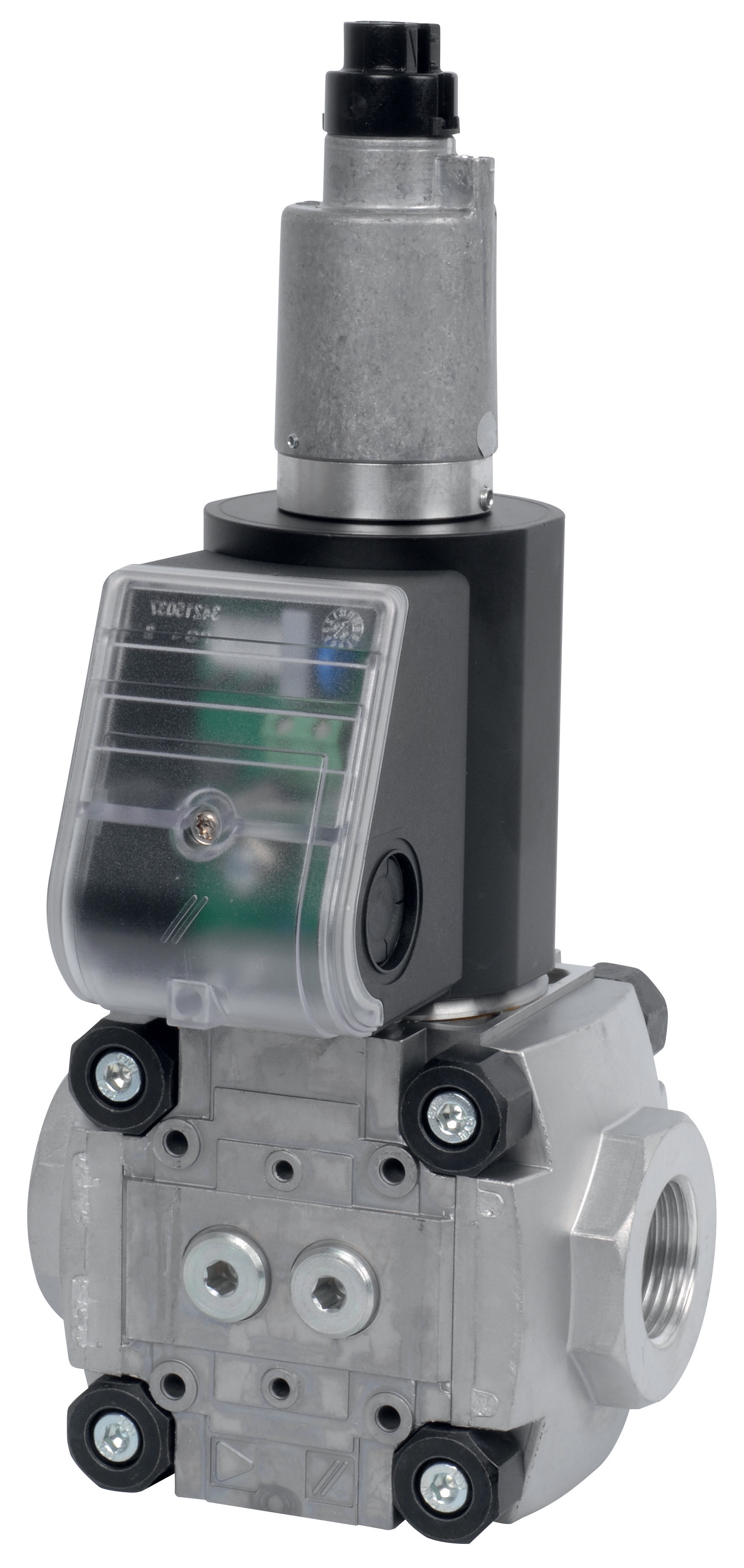
For the CBM Fast gas solenoid valve VAS 110R/NW, expect electrical response times of 8-12 milliseconds under ideal conditions. The CBM Slow gas solenoid VAS 125R/LW typically shows 15-25 millisecond electrical response.
Phase 2: Mechanical Response Time Measurement
Mechanical response time includes the valve plunger travel time and represents the actual system performance:
1. Connect a regulated gas supply (typically 2-5 bar) to the solenoid valve inlet during testing
2. Position the pressure transducer at the valve outlet
3. Apply the 24 VDC control signal while simultaneously monitoring pressure transducer output
4. Identify the point where outlet pressure begins rising (indicates plunger lift-off)
5. Measure time from control signal rising edge to 10% outlet pressure rise (this indicates plunger movement begins)
6. Continue measurement until full outlet pressure is achieved (90% of inlet pressure)
7. Total mechanical response time is the sum of electrical response plus plunger travel time
8. Repeat 10 cycles and document consistency
Total mechanical response times typically range from 30-80 milliseconds depending on valve type and gas pressure conditions.
Phase 3: Reset Time Verification
Reset time (closure response) is equally critical to Controls & Safety performance:
1. While the solenoid is energized and the valve is fully open, remove the 24 VDC control signal
2. Observe the outlet pressure transducer as the plunger returns to seating position
3. Measure time from control signal removal to 90% pressure drop at outlet
4. Document typical reset times (usually 40-120 milliseconds)
5. Perform 10 cycles to identify consistency
Inconsistent reset times indicate plunger stiction or debris accumulation in the valve body, requiring immediate service or replacement.
Phase 4: Temperature Compensation Testing
Response times vary significantly with ambient temperature. Comprehensive testing includes:
1. Perform baseline measurements at 20°C ambient temperature
2. Heat test environment to 40°C and repeat all measurements
3. Cool test environment to 0°C (if applicable to your operating geography) and repeat measurements
4. Document response time variance across temperature range
5. Maximum acceptable variance is typically ±10% across the operating temperature range
Greater temperature sensitivity indicates weakening electrical connections or plunger wear requiring attention.
Interpretation of Results and Maintenance Recommendations
Establishing Your Baseline and Acceptance Criteria
New solenoid valves should be tested immediately upon receipt to establish baseline response times. Create a maintenance record documenting:
- Electrical response time (milliseconds)
- Mechanical response time (milliseconds)
- Reset time (milliseconds)
- Temperature sensitivity coefficient
- Pressure sensitivity at 2, 3, and 5 bar inlet pressure
Establish acceptance criteria at 20% above measured baseline values. For example, if a new CBM Slow gas solenoid valve VAS 340R/LW measures 50 milliseconds mechanical response, your alert threshold becomes 60 milliseconds.
Identifying Degradation Patterns
Regular response time trending reveals maintenance needs before safety failures occur:
- Gradual increase (5-15% per quarter): Normal aging, schedule replacement during next planned maintenance window
- Sudden jump (>20% increase): Electrical connection deterioration or internal debris, requires immediate inspection
- High variability (>10% deviation between cycles): Plunger stiction or spring fatigue, plan valve service
- Temperature sensitivity increase: Electrical winding degradation, recommend replacement within 30 days
- Asymmetric response (opening faster than closing): Plunger wear or spring weakness, replacement required
Solenoid valves rarely operate in isolation. The CBM Relay DMG 970-N MOD.03 and similar control relays introduce additional system response time. Test the complete chain:
1. Apply flame failure signal to the relay input
2. Measure time from signal interruption to solenoid deenergization at relay output
3. Add this relay response time to solenoid response time for total system response
4. Ensure combined response time meets equipment manufacturer specifications (typically <300 milliseconds for burner safety systems)
Documentation and Compliance Requirements
Maintain permanent records of all response time measurements:
- Test dates and times
- Environmental conditions (temperature, pressure, humidity)
- Technician identification
- Measured values and comparison to baseline
- Corrective actions taken
- Next scheduled test date
These records demonstrate Controls & Safety compliance during audits and investigations and provide the technical foundation for warranty claims if premature failures occur.
Practical Maintenance Actions Based on Test Results
When to Service Versus Replace
Not all response time degradation requires replacement. Minor response time increases (5-10%) often respond to cleaning and adjustment:
- Remove solenoid coil and inspect for corrosion or moisture
- Clean plunger rod with soft cloth; do not use abrasive materials
- Verify spring action by manual actuation
- Check valve outlet for debris or mineral buildup
- Reinstall and retest
However, if response times exceed your established alert thresholds after cleaning, or show sudden increases >20%, replacement is necessary. Attempting to nurse along a failing solenoid risks catastrophic safety failure.
Preventive Replacement Strategies
Based on your response time trending data, establish preventive replacement intervals. For example:
- Equipment operating 24/7 with fast-response solenoids: Replace every 3-4 years
- Seasonal equipment with slow-response valves: Replace every 5-6 years
- Process equipment with variable duty: Replace when response time reaches 80% of alert threshold
This approach prevents emergency failures and maintains Controls & Safety reliability.
Training Your Maintenance Team
Response time testing requires technical skill and consistency. Establish formal training covering:
- Oscilloscope operation and signal interpretation
- Safe handling of gas systems and electrical components
- Calculation and documentation procedures
- Trend analysis and decision-making criteria
- Equipment-specific testing variations
Invest in certification training for at least two team members to ensure continuity and knowledge preservation.