Understanding Controls & Safety Valve Technologies in HVAC Systems
Controls & Safety components form the critical decision-making layer of modern HVAC burner systems. Unlike simple on-off switches, contemporary gas solenoid valves incorporate sophisticated response characteristics that directly influence system performance, safety compliance, and operational efficiency. For HVAC contractors managing installations across diverse commercial and industrial environments, understanding the technical distinctions between valve types determines whether a system performs optimally or operates at reduced capacity.
At 3G Electric, our 35+ years of experience distributing industrial equipment has demonstrated that Controls & Safety valve selection represents one of the most underestimated technical decisions in burner system design. Contractors frequently focus on burner capacity without adequate consideration of the solenoid valve's ability to modulate gas flow within the required response window. This article addresses that knowledge gap by providing practical, application-specific guidance.
Fast Response Solenoid Valves: Applications and Performance Characteristics
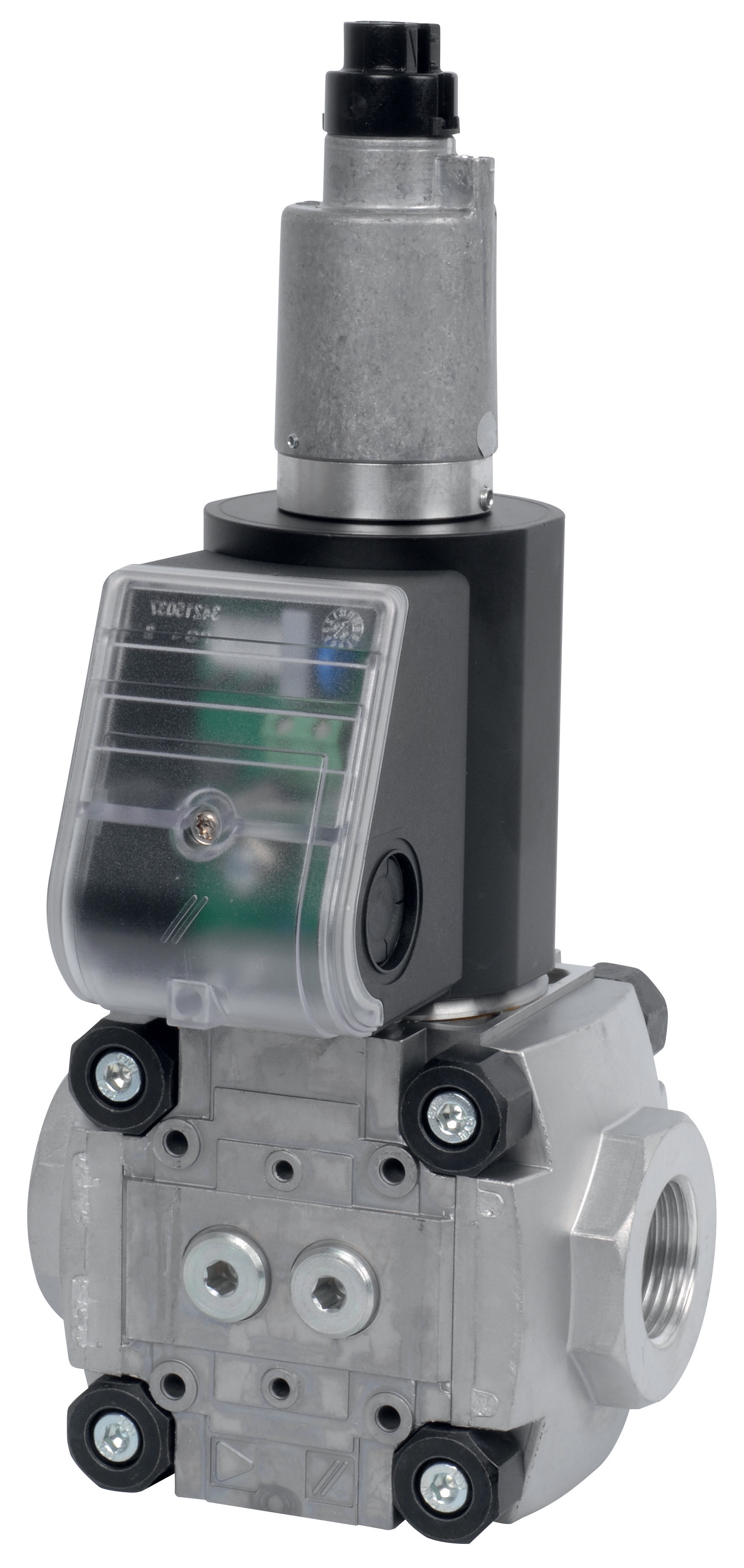
Fast-response solenoid valves, exemplified by the CBM Fast gas solenoid valve VAS 110R/NW and CBM Fast gas EV VAS 365R/NW, deliver gas to the burner primary chamber within milliseconds of receiving an electrical signal. These valves activate in approximately 50-80 milliseconds, creating the rapid gas pressure rise necessary for prompt ignition in compact burner designs.
Performance specifications for fast-response variants:
- Response time: 50-80 milliseconds from coil energization to full valve opening
- Pressure differential range: Typically 0.5-3.5 bar operating window
- Flow rate capacity: VAS 110R/NW rated for 30-50 m³/h; VAS 365R/NW accommodates 80-120 m³/h
- Orifice design: Precision-calibrated for minimal pressure drop across valve seat
- Application profile: Compact commercial units, modular burners, rapid-cycle systems
Fast-response Controls & Safety valves excel in scenarios where the burner chamber volume is restricted and ignition must occur within strict timing parameters. In retrofit applications where existing ductwork and combustion chambers cannot be modified, the rapid valve response compensates for inherent system characteristics that would otherwise cause delayed ignition or incomplete fuel-air mixing.
Contractors should specify fast-response valves when:
- Installation occurs in confined spaces with limited combustion chamber volume
- Existing flame detection systems require rapid fuel delivery for reliable pilot light establishment
- The burner operates in modulating mode with frequent on-off cycling
- Safety interlocks demand fast shutdown capability—though fast opening also requires fast closing characteristics
- The system design calls for minimal pressure lag between valve command and actual gas delivery
Slow Response Solenoid Valves: Benefits for High-Capacity and Regulated Operations
Slow-response solenoid valves, including the CBM Slow gas solenoid VAS 125R/LW and CBM Slow gas solenoid valve VAS 340R/LW, operate with intentionally gradual opening characteristics spanning 200-350 milliseconds. This deliberate delay serves multiple critical functions in larger burner installations and systems requiring precise gas flow regulation.
Technical specifications for slow-response designs:
- Response time: 200-350 milliseconds with graduated opening curve
- Pressure differential: Designed for stable operation across 0.8-4.0 bar range
- Flow capacity: VAS 125R/LW handles 50-80 m³/h; VAS 340R/LW supports 120-200 m³/h installations
- Solenoid coil design: Higher inductance reduces electrical switching transients
- Safety integration: Damping characteristics prevent pressure spikes in coupled dual-valve arrangements
The seemingly counterintuitive design decision to slow solenoid valve response actually enhances Controls & Safety performance in several critical areas. Large commercial burners with substantial combustion chamber volumes benefit from gradual gas introduction because instantaneous full-flow valve opening creates pressure surges that destabilize the flame front and compromise combustion efficiency. The slow-response characteristic allows the combustion process to establish in a controlled manner.
Slow-response valve applications include:
- Industrial boilers rated above 1 MW thermal input
- Burners equipped with modulating capacity-control systems
- Dual-stage burner configurations where primary and secondary valves must operate sequentially
- Systems coupled with proportional flow control blocks requiring steady pressure delivery
- Installations where electrical noise immunity is critical—slow coil energization reduces EMI radiation
Controls & Safety Relay Integration: The DMG 970-N Modulation and Safety Hub
The CBM Relay DMG 970-N MOD.03 represents the intelligence layer coordinating solenoid valve operations with safety inputs. This relay module processes signals from flame detection circuits, temperature sensors, and limit switches, then delivers appropriately timed commands to solenoid valves based on both fast and slow response characteristics.
Critical DMG 970-N functional capabilities:
- 24VDC control circuit with integrated safety relay functionality
- Adjustable timing sequences accommodating both fast and slow valve response windows
- Flame monitoring input supporting infrared and photo-resistive cell detection methods
- Dual-output relay contacts enabling simultaneous or sequential solenoid valve energization
- Automatic shutdown logic with forced-draft reset requiring positive command signal
- Modulation input for capacity-control integration (0-10V proportional signal)
When specifying Controls & Safety systems, the relay module selection must account for solenoid valve response characteristics. If a contractor installs a slow-response valve but pairs it with a relay expecting fast valve behavior, the burner's ignition sequence becomes unreliable. Conversely, pairing a fast-response valve with delay-oriented relay logic causes unnecessary energy consumption during extended valve-opening times.
The DMG 970-N's modular design (MOD.03 variant) includes plug-in option cards configuring:
- Flame signal sensitivity thresholds
- Solenoid valve command timing sequences
- Safety lockout duration after ignition failure
- Modulation ramp rates for capacity control integration
This flexibility allows HVAC contractors to adapt the same relay module across diverse installation scenarios, from compact commercial units using fast-response valves to large industrial burners requiring slow, regulated gas introduction.
Practical Selection Framework: Matching Valve Response to Burner Requirements
Effective Controls & Safety system design requires systematic evaluation of burner characteristics before component selection. The following framework guides contractor decision-making:
Step 1: Determine Combustion Chamber Volume and Geometry
Measure the burner's primary combustion chamber from the solenoid valve outlet to the flame stability point. Chambers smaller than 0.5 liters typically require fast-response valves to achieve reliable ignition within acceptable time windows. Chambers exceeding 2.0 liters benefit from slow-response characteristics that allow pressure stabilization before flame establishment.
Step 2: Evaluate Existing Flame Detection Infrastructure
Infrared flame detection cells respond rapidly (within 50-100 milliseconds) to established flames, requiring fast gas delivery to establish combustion before the safety module times out. Photo-resistive cells exhibit longer response latency (150-250 milliseconds), accommodating slower valve opening as long as combustion initiates within the monitored window.
Step 3: Assess Duty Cycle and Modulation Requirements
Burners operating in continuous-modulation mode (capacity-controlled systems adjusting output from 30-100%) benefit from slow-response valves because the gradual opening characteristic enables proportional gas flow without pressure oscillations. Fixed-capacity or simple two-stage burners function adequately with fast-response valves.
Step 4: Calculate System Pressure Differential
Determine the available pressure at the solenoid valve inlet (post-regulator) and the required outlet pressure for stable combustion. Fast-response valves tolerate wide differential ranges but with higher pressure-drop penalties. Slow-response valves optimize for narrow differential windows but provide stable operation within those boundaries.
Step 5: Cross-Reference Safety Standards and Local Codes
European EN 676 and North American CSA B140.3 standards specify maximum allowable ignition failure detection times. Your solenoid valve response characteristics must guarantee combustion establishment within these windows. The relay module (DMG 970-N) provides programmable timing to accommodate valve response variations, but the valve itself must meet baseline requirements.
Commissioning and Maintenance Considerations for Controls & Safety Systems
Installing the correct solenoid valve and relay components represents only the first phase of reliable Controls & Safety performance. Commissioning procedures must validate that the installed configuration achieves ignition within specified windows.
Critical commissioning steps:
- Measure actual solenoid valve opening time using a high-speed pressure transducer at the valve outlet
- Confirm flame detection signal arrival within 100 milliseconds of solenoid energization
- Perform repeated ignition cycles (minimum 20 cycles) documenting any timing variations
- Adjust relay module timing parameters to accommodate measured valve response characteristics
- Document baseline performance metrics for future troubleshooting reference
Regular maintenance of Controls & Safety components includes:
- Annual cleaning of solenoid valve orifice plates to prevent carbon accumulation affecting response time
- Coil insulation testing on relays every 24 months to verify moisture ingress hasn't compromised safety functionality
- Flame detection cell lens cleaning (quarterly in dusty environments) ensuring optical coupling remains within sensitivity specifications
- Pressure regulator inspection confirming inlet-outlet differential stability
3G Electric's technical support team, drawing on 35+ years of industrial equipment expertise, recommends establishing preventive maintenance protocols specific to your solenoid valve and relay combinations. Controls & Safety performance degrades gradually; regular validation against baseline measurements identifies issues before they compromise system safety.
Conclusion: Strategic Controls & Safety Component Selection
The distinction between fast and slow solenoid valve response times appears subtle in technical specifications but profoundly impacts real-world burner performance. HVAC contractors who understand these distinctions specify systems delivering reliable ignition, efficient combustion, and robust safety compliance across diverse installation environments.
The fast-response valves VAS 110R/NW and VAS 365R/NW excel in compact, space-constrained applications. The slow-response variants VAS 125R/LW and VAS 340R/LW provide superior performance in high-capacity and modulating systems. The DMG 970-N MOD.03 relay module adapts to both valve types, optimizing the Controls & Safety sequence for your specific burner design.
By matching valve response characteristics to burner geometry, flame detection methods, and duty cycles, contractors eliminate the most common source of ignition failures and safety system nuisance shutdowns. This technical approach, informed by 3G Electric's three decades of industrial equipment distribution, positions your installations for reliable, efficient operation throughout their service lives.