Understanding Controls & Safety in Industrial Burner Systems
Controls & Safety represents the critical intersection of operational reliability and regulatory compliance in industrial combustion equipment. For procurement engineers managing global operations, understanding how individual control components function as an integrated system is essential for selecting equipment that meets both performance specifications and safety standards.
At 3G Electric, our 35+ years of experience distributing industrial equipment has shown us that most failures in burner control systems stem not from individual component defects, but from improper integration or mismatched component selection. A pilot light may function perfectly in isolation, but if it's not properly matched to your solenoid valve characteristics and relay logic, the entire safety chain breaks down.
The Controls & Safety ecosystem comprises several interdependent components: solenoid valves that regulate gas flow, pilot lights that provide ignition sources, relays that manage electrical switching logic, and the control bases that house these elements. Each component must be selected not only for its individual specifications but for how it integrates with the others.
Solenoid Valves: The Foundation of Safe Gas Control
Solenoid valves are the primary mechanism through which Controls & Safety systems regulate gas flow. These electromagnetic devices open and close in response to electrical signals, providing fail-safe operation when properly integrated with your control logic.
The CBM VCS 1E25R/25R05NNWL3/PPPP/PPPP double solenoid valve represents a critical procurement consideration for several reasons. Double solenoid configurations provide redundancy—one solenoid can serve as the primary control valve while the second acts as a safety shutoff valve. This architecture ensures that even if one solenoid fails in the open position, the second solenoid can still close the gas supply.
When procuring solenoid valves, procurement engineers must verify:
- Flow capacity ratings align with your burner's maximum fuel consumption
- Pressure drop characteristics are acceptable for your system pressure range
- Coil voltage compatibility matches your control system's electrical specification (typically 24V DC for safety-critical applications)
- Response time meets your ignition and flame supervision requirements
- Port sizes correspond to your piping infrastructure
The double solenoid configuration adds complexity but provides genuine safety benefits. The pilot solenoid (smaller flow) controls a pilot flame, while the main solenoid (larger flow) controls the primary burner gas supply. If flame detection fails, the main solenoid closes immediately, but the pilot solenoid can remain open to facilitate reignition attempts.
From a procurement perspective, this means you cannot simply select a solenoid valve based on flow rating alone. You must understand your complete control sequence: does your system require manual pilot ignition followed by automatic burner ignition? Does it require intermittent pilot operation (pilot lights only when main flame is active)? These decisions directly impact which solenoid configuration you need.
Pilot Lights and Ignition Control: Precision Components with Safety-Critical Functions
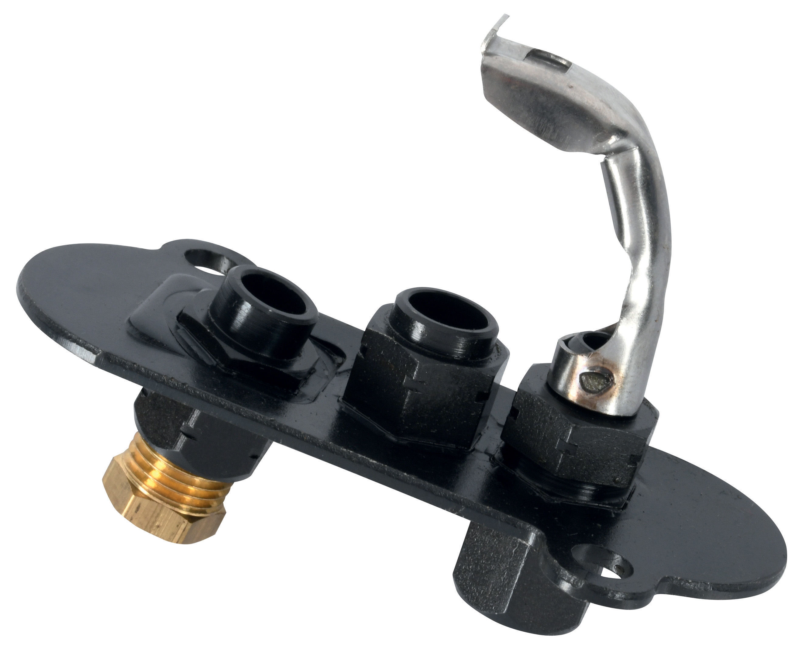
Pilot lights serve as both reliability and safety devices. They provide a continuous or intermittent ignition source for the main burner, and in flame supervision systems, they provide a signal point for flame detection sensors.
Two primary pilot light options commonly appear in modern burner controls. The CBM 1-flame pilot light 0.150.082 and the CBM Pilot light 1 flame 0140026 serve similar functions but with different mounting and performance characteristics.
Pilot light selection impacts your Controls & Safety system in several ways:
- Thermal output: Pilot lights produce heat that may or may not be captured by your heat exchanger. Oversized pilots waste fuel; undersized pilots may not provide sufficient ignition energy
- Sensor coupling: If you use photoresistive or infrared flame detection, the pilot light's flame characteristics (color, intensity, flicker pattern) directly affect sensor reliability
- Flame stability: Different pilot designs produce different flame stability characteristics. A pilot with poor flame stability can trigger nuisance shutdowns in windy installations
- Maintenance access: Pilot light cartridge replacement frequency varies significantly between designs. In remote locations, selecting a more robust pilot design reduces service visits
For procurement engineers, pilot light selection should consider the broader control strategy. If your system uses electronic flame detection, you must coordinate pilot light specifications with sensor requirements. A flame detection system that works perfectly with one pilot light design may fail intermittently with another due to flame spectrum differences.
Pilot lights also represent a potential failure point in Controls & Safety systems. Many specifications require that loss of pilot flame triggers an immediate safety shutdown (pilot flame supervision). This means your pilot light reliability directly impacts system availability.
Relay Logic and Control Bases: Integrating Electrical Switching
The CBM Relay CM391.2 30.5 1.2 and CBM Base LGK AGM17 represent the electrical switching intelligence that coordinates your entire control system. These components translate sensor inputs into solenoid valve commands, manage timing sequences, and enforce safety interlocks.
Relay-based control systems (as opposed to programmable logic controllers) offer specific advantages for industrial burner applications:
- Fail-safe operation: Relay logic can be architected so that loss of electrical power results in safe shutdown, not safe operation
- Simple diagnostics: When a relay-based system fails, troubleshooting is often straightforward—test voltage at each contact point
- Regulatory acceptance: Many industrial safety standards explicitly recognize relay-based control systems as acceptable for critical functions
- Cost-effectiveness: For simple on-off-shutdown control sequences, relay systems often cost less than programmable alternatives
The control base provides standardized mounting for relays, solenoids, and other electrical components. Selection of the correct base prevents procurement of incompatible components and reduces installation errors. The CBM Base LGK AGM17 must be verified for compatibility with your specific relay model and environmental requirements.
Relay specifications require careful attention to several parameters:
Contact Rating: Relays are rated for maximum switching current at specific voltages. A relay rated for 24V DC may not safely switch 120V AC circuits—the current-carrying capacity differs significantly between AC and DC.
Timing Functions: Modern relays often include timing elements—off-delay timers that prevent rapid on-off cycling, on-delay timers that allow pilot stabilization before main flame ignition attempts. Your procurement specification must clearly state which timing functions your control sequence requires.
Safety-Rated Contacts: Some applications require redundant contacts where both must close before the solenoid energizes. This provides verification that the relay has actually switched, improving safety integrity.
For procurement engineers, understanding your control sequence before selecting relays is essential. The minimum acceptable configuration typically includes:
- Pilot solenoid control (manual or automatic ignition)
- Main burner solenoid control (with delay after pilot establishment)
- Flame supervision shutoff (immediate closure if flame is lost)
- Reset logic (manual reset required after safety shutoff)
Practical Integration Considerations
With 35+ years of experience as a global industrial equipment distributor, 3G Electric has observed common integration failures that reduce Controls & Safety system reliability:
Voltage incompatibility: Procuring a 110V solenoid coil for a 24V DC control system. Always verify that all control components operate at the same voltage specification.
Response time mismatches: Selecting a solenoid with 500ms response time when your control logic expects 50ms response. The timing gap prevents proper sequence execution.
Redundancy conflicts: Using non-redundant components in positions where safety standards require redundancy. If your standard requires redundant solenoids, both must be specified and installed.
Environmental specification gaps: Installing components rated for 40°C maximum in environments that reach 60°C. Operating temperature directly impacts component reliability and safety function.
Maintenance accessibility: Specifying components that require specialized tools or proprietary parts for routine maintenance. When maintenance becomes difficult, it gets deferred, reducing system reliability.
Procurement engineers should develop specifications that include not only component performance parameters but also lifecycle considerations: availability of replacement parts, training requirements for maintenance staff, compatibility with existing installations, and regulatory documentation requirements.
Conclusion
Controls & Safety systems succeed when all components—solenoid valves, pilot lights, relays, and control bases—are selected as an integrated architecture rather than as individual components. The solenoid valve, pilot lights, relays, and control bases from CBM represent industry-standard components that, when properly integrated, provide reliable and compliant burner system operation across global installations.
Your procurement strategy should prioritize compatibility verification, environmental suitability, and long-term maintainability alongside initial cost considerations. The cost of a component failure in a safety-critical system far exceeds the savings from selecting lower-cost alternatives that lack proper integration.