Controls & Safety: A Procurement-Focused Guide to Solenoid Valves and Relay Systems
When specifying Controls & Safety components for industrial gas burner systems, procurement engineers face critical decisions that impact equipment reliability, regulatory compliance, and operational costs. Solenoid valves and safety relays form the backbone of automated burner control systems worldwide, yet many procurement professionals lack frameworks for evaluating competing options or understanding application-specific requirements.
At 3G Electric, we've supported global industrial operations for over 35 years, helping procurement teams navigate complex controls & safety specifications across diverse markets and regulatory environments. This guide translates technical requirements into practical procurement strategies, enabling you to make informed decisions that balance performance, compliance, and total cost of ownership.
Section 1: Understanding Solenoid Valve Types and Specification Requirements
Response Speed and Application Matching
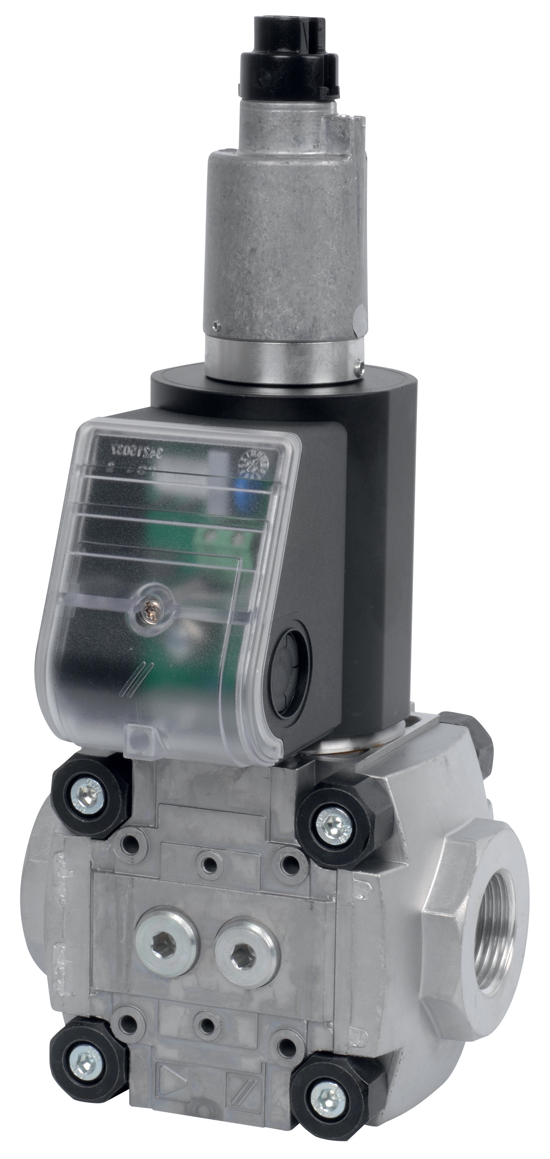
Solenoid valve selection begins with understanding your burner system's operational demands. Industrial gas burner controls require two distinct solenoid valve categories: fast-acting valves for primary gas isolation and slow-acting valves for modulating control.
Fast-acting solenoid valves respond in milliseconds, making them essential for safety shutoff functions. These valves must open or close almost instantaneously when the control system signals a change, protecting equipment from flame failure or overpressure conditions. The CBM Fast gas solenoid valve VAS 110R/NW and CBM Fast gas EV VAS 365R/NW deliver this rapid response across different flow capacities, with the VAS 110R/NW suited for smaller burners and the VAS 365R/NW handling larger capacity systems.
Slow-acting solenoid valves, conversely, modulate gas flow gradually over 3-8 seconds, preventing pressure spikes and flame instability in main burner lines. This controlled response is critical for burner efficiency and combustion quality. The CBM Slow gas solenoid VAS 125R/LW and CBM Slow gas solenoid valve VAS 340R/LW provide this modulating function across different inlet pressures and flow ranges.
Key Specification Parameters for Procurement
When evaluating solenoid valve proposals, establish clear specification criteria:
Flow Capacity: Match valve flow ratings (Cv or Kvs values) to your burner's maximum gas consumption plus 10-15% safety margin. Undersized valves create backpressure, affecting burner stability. Oversized valves waste cost and energy.
Operating Pressure Range: Verify the valve maintains 100% sealing across your system's minimum to maximum operating pressures. Many procurement failures occur when valves selected for "typical" pressures encounter peak conditions during cold starts or load transients.
Voltage and Power Consumption: Confirm solenoid coil voltage compatibility with your facility's electrical infrastructure. Record power consumption to ensure control panel circuits carry adequate capacity without nuisance breaker trips.
Sealing Material: Chemical compatibility between valve internals and your gas type is non-negotiable. Propane, natural gas, and mixed fuels require different elastomer specifications. Incorrect sealing materials lead to leakage and safety violations.
Response Time Certification: Request independent test certificates confirming response times under actual operating conditions, not theoretical minimums. Real-world response performance directly impacts burner stability and safety margin.
Vendor Evaluation Framework
Evaluate solenoid valve suppliers using these assessment criteria:
- Certification and Standards Compliance: Verify CE, UL, or regional certifications appropriate to your market. Confirm compliance with EN 161 (gas safety), ASME code (where applicable), and local regulatory requirements.
- Technical Documentation Quality: Request detailed datasheets including pressure-flow curves, response time graphs, and sealing material specifications. Poor documentation indicates either immature products or unreliable suppliers.
- Local Service Network: Confirm the supplier maintains technical support, spare parts availability, and emergency service within your operational region. A 6-month lead time on valve replacements is unacceptable for critical safety equipment.
- Reference Installations: Request contact information for installations similar to yours (same industry, comparable burner capacity, comparable duty cycle). Direct conversations with existing users reveal real-world reliability patterns vendors won't mention.
Section 2: Safety Relay Systems and Control Logic Integration
The Role of Safety Relays in Burner Controls
Modern burner controls integrate solenoid valves through safety relay modules that monitor multiple input conditions—flame detection, pressure switches, limit switches—and execute predetermined shutoff sequences when faults occur. The CBM Relay DMG 970-N MOD.03 exemplifies industrial-grade relay modules designed for this critical function.
Unlike simple electromechanical relays, safety relays incorporate redundant monitoring circuits that verify each other's operation. This self-checking capability ensures that a failed relay contact cannot mask a safety condition—the system fails safe by shutting down fuel supply.
Specifying Safety Relay Modules
When selecting safety relays for your control systems, address these procurement requirements:
Safety Category Rating: European EN 954-1 defines five safety categories (B, 1, 2, 3, 4). Your application's hazard analysis determines required category. Burner systems typically require Category 3 (high reliability with single fault tolerance) or Category 4 (highest reliability). Confirm your relay module achieves this rating through independent test reports.
Input Configuration Flexibility: Different burner applications require different monitoring logic. Some systems monitor two flame sensors for redundancy; others integrate pressure safety switches, draft switches, and temperature limiters. Select relay modules with configurable input channels and adjustable timing functions rather than fixed-function devices.
Fail-Safe Output Design: Verify that all safety shutoff outputs remain de-energized upon power loss. Any relay failure or electrical fault must result in fuel valve closure. Test this requirement in your facility's electrical environment—some locations experience unusual transients that can compromise fail-safe operation.
Response Time Verification: Safety relays must execute shutoff sequences within defined time windows. Most regulations require main fuel valve closure within 1-2 seconds of flame loss detection. Request independent test certificates confirming this performance.
Modular Architecture: Prefer relay modules with interchangeable sub-modules for flame sensors, input cards, and output cards. This modularity reduces downtime when component replacement is needed and simplifies future upgrades.
Integration with Solenoid Valve Systems
Safety relays and solenoid valves form an integrated system where relay response time must coordinate with valve closing speed. This coordination prevents pressure spikes and ensures reliable fault shutdown.
When the safety relay detects a fault condition, it de-energizes solenoid valve coils controlling pilot and main gas supplies. The fast-acting solenoid (like the VAS 110R/NW) closes pilot fuel immediately—typically within 100-150ms. The slow-acting solenoid (like the VAS 125R/LW) closes main fuel over 3-5 seconds, allowing backpressure to bleed safely through pilot lines rather than causing equipment shock.
This coordinated response protects downstream equipment, prevents dangerous pressure transients, and satisfies regulatory shutdown requirements. Mismatched valve selection—using only fast-acting valves, for example—creates sudden pressure drops that destabilize pilot flames and increase nuisance shutdowns.
Section 3: Installation, Testing, and Compliance Verification
Pre-Installation Requirements
Before solenoid valves and safety relays are installed, establish clear protocols:
System Pressure Verification: Have the equipment manufacturer confirm that installed solenoid valves are rated for your specific inlet and outlet pressures. Field conversions between natural gas and propane systems often involve pressure range changes that exceed original valve ratings.
Electrical Supply Compatibility: Measure actual voltage at the solenoid coil terminals under full load conditions (burner running, pilot flame ignited). Voltage drop across control wiring can reduce coil force by 20-30%, preventing reliable operation. Correct undersized wiring before installation.
Gas System Cleanliness: Run a system purge before installing solenoid valves, flushing ferrous particles and flux residue that corrode valve internals. Dirty gas is the leading cause of solenoid valve failure in new installations.
Orientation and Mounting: Solenoid valves must be installed in specified orientations—coil upward for most designs. Horizontal or inverted mounting can trap moisture and prevent reliable operation. Confirm mounting position matches the valve's internal design.
Functional Testing Protocol
Develop testing procedures that verify both individual component function and integrated system performance:
Solenoid Valve Testing:
- Measure coil resistance under no-load conditions; compare against manufacturer specification (typically ±10% tolerance)
- Verify valve seals holding zero leakage under full inlet pressure for 1 minute
- Confirm valve opens and closes smoothly through 10 complete cycles
- Record opening and closing response times with independent test equipment
- Simulate each monitored input condition (flame detection loss, pressure switch activation) and verify corresponding solenoid de-energization
- Confirm manual fuel shutoff button immediately de-energizes safety relays
- Verify that loss of electrical power immediately de-energizes safety shutoff solenoids
- Test interlock logic: some systems require simultaneous monitoring of multiple conditions before fuel isolation
- Run the burner system through complete startup and shutdown sequences
- Induce fault conditions (simulate flame loss, trigger pressure switches) and verify fuel shutoff occurs within specified time
- Confirm pilot flame extinguishes within 2 seconds of solenoid de-energization
- Measure pressure decay rates downstream of both fast and slow solenoids
Documentation and Compliance Records
Maintain detailed records demonstrating compliance with local regulations:
- Test certificates from solenoid valve and relay manufacturers confirming performance ratings
- Pressure and temperature profiles from your installed system
- Functional test results documenting response times and fault shutoff sequences
- Maintenance logs recording inspection intervals and any component replacements
- Regulatory inspection reports from local authorities having jurisdiction
These records prove due diligence if safety incidents occur and satisfy audit requirements from insurance carriers and regulatory bodies.
Section 4: Lifecycle Management and Total Cost Optimization
Spare Parts Strategy
Develop predictive spare parts policies based on Mean Time Between Failures (MTBF) data:
Critical Spares: Maintain in-stock replacement solenoid valves matching your burner system's capacity and response speed requirements. A failed fuel solenoid takes the entire burner offline—inventory cost is negligible compared to production downtime.
Common Failure Modes: Track which components fail most frequently in your application. If solenoid coils fail more often than valve internals, stock additional coil assemblies (often available separately from complete valves). If sealing surfaces fail, consider uprating to premium seal materials even if costs increase 15-20%.
Supplier Lead Times: Document actual lead times from each vendor in your region. If standard delivery exceeds 4 weeks, increase safety stock proportionally or establish emergency procurement contracts for premium delivery costs.
Preventive Maintenance Intervals
Establish maintenance schedules balancing reliability against cost:
Annual Inspections: At minimum, solenoid valves should be visually inspected annually for corrosion, leakage, or coil damage. Safety relays should be functionally tested to confirm all monitored inputs execute correct shutoff logic.
Biennial Calibration: Pressure switches and flame detection sensors drift over time. Professional calibration every 24 months ensures detection setpoints remain within regulatory tolerances.
Component Replacement Thresholds: Many procurement engineers delay valve replacement until failure occurs. Superior practice establishes replacement thresholds based on age and duty cycle: valves in continuous duty should be replaced every 5-7 years regardless of apparent condition; seasonal systems may extend to 10 years. This proactive replacement prevents catastrophic failures and system instability.
Vendor Partnership Development
Transform supplier relationships from transactional to strategic:
- Schedule quarterly business reviews with your solenoid valve and relay suppliers, discussing failure patterns, new product capabilities, and cost reduction opportunities
- Negotiate volume commitments in exchange for favorable pricing and preferential emergency support
- Participate in supplier training programs to deepen your engineering team's technical knowledge
- Provide feedback on product performance, highlighting both successes and improvement opportunities
Suppliers like 3G Electric, with 35+ years of global distribution experience, invest in customers who engage strategically rather than seeking only lowest price.
Section 5: Regional Regulatory Considerations
European Market Requirements
European Union regulations mandate CE marking for gas safety components, requiring compliance with EN 161 (control components for gas burners and gas appliances), EN 954-1 (safety control systems), and ATEX directives for explosive atmospheres. Solenoid valves and safety relays must carry test certificates from Notified Bodies—not in-house manufacturer certifications.
Select suppliers maintaining current documentation and certification status. Regulatory enforcement has intensified significantly since 2020, with fines reaching €50,000+ for non-compliant equipment installation.
Asian Market Variations
Singapore, Malaysia, and Indonesia follow mixed regulatory frameworks incorporating British Standards (BS 5885) with local amendments. Confirm your supplier's certifications align with the specific country's requirements—a valve certified for EU markets may lack required Singapore Technical Committee approval.
Americas Market Requirements
United States and Canadian markets typically require CSA or UL certification for safety components. Unlike European Notified Body requirements, CSA/UL certifications can come from manufacturers' own testing facilities, simplifying compliance documentation.
Practical Implementation Checklist
Before finalizing solenoid valve and safety relay specifications:
- Define Response Requirements: Document required shutdown response time, pilot modulation speed, and pressure range tolerance
- Identify Monitoring Inputs: List all conditions requiring monitoring (flame detection, pressure switches, limit switches) to determine safety relay configuration needs
- Establish Compliance Standards: Confirm which regional certifications and standards apply to your market
- Request Technical Documentation: Require pressure-flow curves, response time graphs, and independent test certificates
- Evaluate Service Network: Confirm spare parts availability and technical support within your region
- Develop Testing Protocol: Create written functional test procedures before equipment arrives
- Establish Maintenance Plan: Define inspection intervals, calibration schedules, and component replacement thresholds
- Plan Training: Schedule vendor training for your maintenance team on troubleshooting and safe replacement procedures