Understanding Controls & Safety in Industrial Burner Systems
Controls & Safety represents one of the most critical system domains in industrial heating equipment. Unlike flame detection or gas regulation alone, a comprehensive Controls & Safety strategy integrates multiple component types working in concert to manage ignition, monitoring, and emergency shutdown functions.
For procurement engineers evaluating equipment for global industrial operations, understanding how double solenoid valves, relay systems, and pilot light components interact is essential. These components don't function in isolation—each plays a specific role in the safety chain, and selecting compatible, reliable products directly impacts system uptime, regulatory compliance, and operational safety.
With over 35 years of experience distributing industrial equipment globally, 3G Electric has guided thousands of procurement professionals through these decisions. This comparison article addresses the practical selection criteria that matter most when specifying Controls & Safety components.
Double Solenoid Valves: The Safety-Critical Gateway
Double solenoid valve configurations represent a fundamental approach to safety in burner control systems. Unlike single solenoid designs, dual-solenoid architectures provide redundancy and fail-safe operation critical for hazardous applications.
The CBM VCS 1E25R/25R05NNWL3/PPPP/PPPP double solenoid valve exemplifies this design philosophy. This component serves as the primary gas supply control and safety shutoff mechanism, capable of:
- Proportional Gas Flow Control: The dual solenoid arrangement allows independent control of gas flow paths, enabling proportional regulation rather than simple on/off switching
- Fail-Safe Closure: If electrical power is lost or a control signal is interrupted, both solenoids de-energize simultaneously, closing gas supply paths
- Redundancy Verification: System logic can command one solenoid while monitoring the second as a backup, confirming functional safety through periodic testing
- International Compliance: PPPP designation indicates certification to multiple international standards, supporting global deployment
Procurement Considerations for Solenoid Valves
When evaluating double solenoid valves, procurement engineers should assess:
Flow Rate Matching: Confirm the valve's rated flow capacity (typically specified in m³/h or similar units) aligns with your burner's fuel demand across all operating conditions. Oversized valves introduce sluggish response; undersized units create backpressure that affects combustion quality.
Pressure Rating: Double solenoid valves operate within specific pressure bands. The CBM VCS series handles medium-pressure gas applications typical of industrial burners. Verify your system's operating pressure against the valve's rated range—pressure excursions can cause seal degradation or solenoid chatter.
Electrical Specifications: The NNWL3 designation indicates specific coil voltage and winding characteristics. Global operations require careful attention to voltage standards (230V AC, 110V AC, 24V DC) to avoid installation conflicts and support voltage variation tolerance across different regions.
Response Time: Dual solenoid response characteristics affect ignition reliability. Slower response times may require adjusted ignition sequences; faster response improves system responsiveness but demands more precise control timing.
Relay Systems: The Logic and Protection Layer
Relay systems form the decision-making infrastructure of Controls & Safety systems. While modern combustion controls increasingly use programmable logic, relay-based systems remain standard in many industrial environments due to their inherent safety properties and proven reliability.
The CBM Relay CM391.2 30.5 1.2 and Its Supporting Base
This relay component functions as a multi-contact switch that:
- Monitors Safety Interlocks: The relay verifies that permissive conditions exist before allowing solenoid valve energization. These might include door switches, high-limit thermostats, low-pressure sensors, or flame detector status.
- Controls Sequence Logic: By energizing and de-energizing in specific patterns, relays implement timed sequences—such as the ignition delay needed before flame detection is expected.
- Provides Time Delay Functions: The 30.5 designation relates to time delay characteristics, allowing programmable wait periods between control steps without requiring electronic timers.
- Delivers Galvanic Isolation: Relay contacts provide electrical isolation between control circuits and load circuits, protecting low-voltage logic from high-current switching transients.
The CBM Base LGK AGM17 serves as the mechanical mounting and electrical connection interface for relay components. Procurement engineers often overlook the relay base, assuming any compatible socket works. In practice, base quality affects:
- Contact Pressure and Material: Quality bases maintain consistent contact force and use silver-cadmium or equivalent materials that resist arcing and oxidation
- Vibration Damping: Industrial environments subject equipment to vibration. Bases with internal dampening reduce contact bounce and false switching
- DIN Rail Compatibility: The AGM17 base mounts on standard DIN rails, ensuring consistency with your control cabinet architecture
- Thermal Management: Bases influence how relay coils dissipate heat. Thermal buildup reduces relay lifetime and increases dropout voltage sensitivity
Relay System Reliability in Global Operations
Relay-based controls offer advantages for international deployment:
Standardization: CBM relay components conform to IEC and equivalent standards recognized across North America, Europe, Asia-Pacific, and Middle East markets. Parts replacement and troubleshooting knowledge transfers readily between regions.
Environmental Tolerance: Unlike sensitive electronic components, quality relays function reliably in temperature extremes (-20°C to +60°C operating range typical), high humidity, and moderate contamination. This matters for remote installations or harsh industrial environments.
Maintenance Accessibility: Procurement teams can stock spare relays and bases as consumable items. Replacement requires only mechanical removal and insertion—no firmware updates, calibration software, or specialized technicians.
Verification Testing: Control system logic implemented through relays can be verified through visual inspection and basic continuity testing. Electronic systems require diagnostic tools and specialized knowledge.
Pilot Lights: The Ignition and Monitoring Foundation
Pilot lights serve dual roles in Controls & Safety systems: they provide the ignition source for the main burner and function as the primary flame presence indicator for safety logic.
3G Electric stocks two CBM pilot light variants, each suited to different burner configurations:
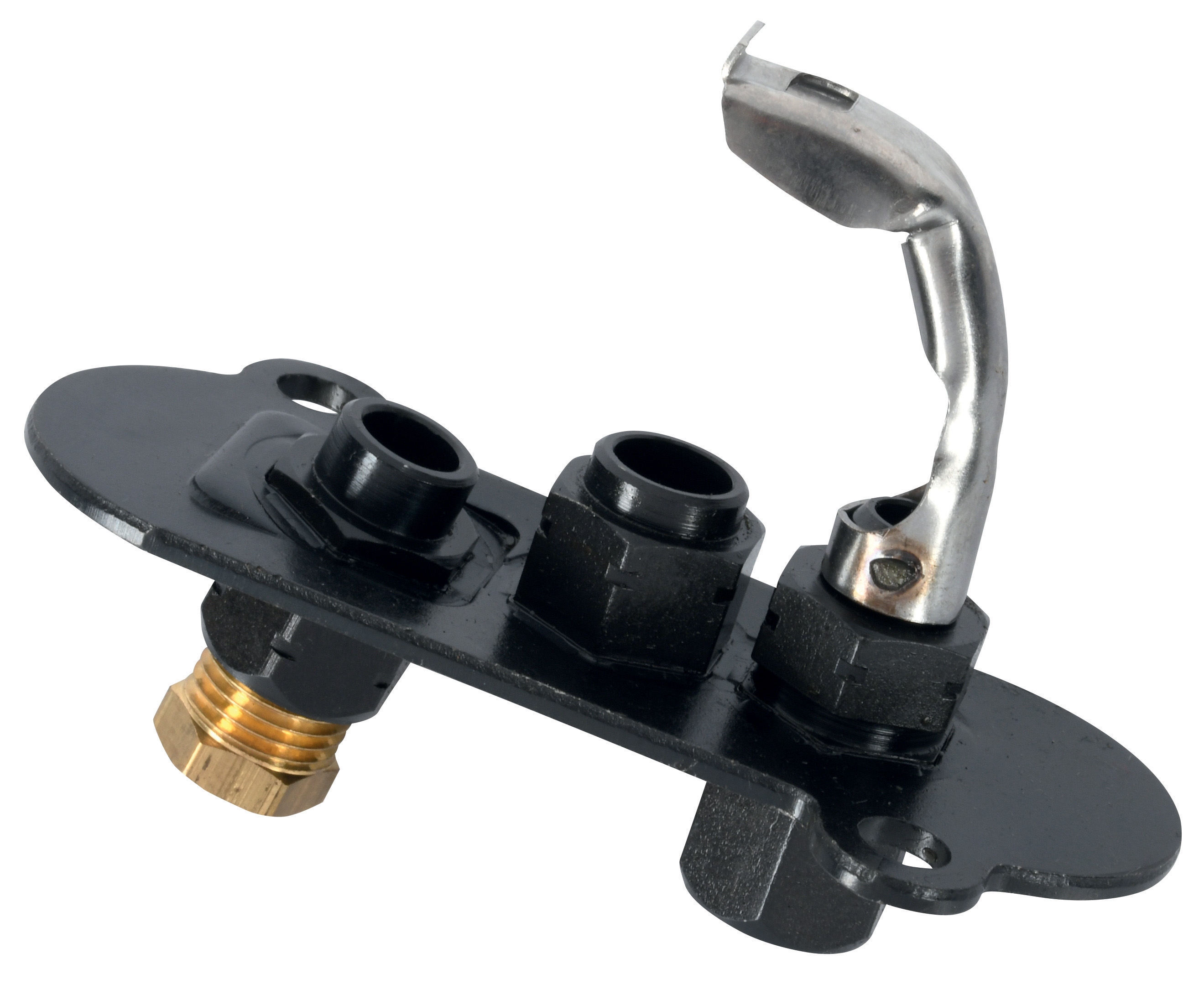
CBM 1-flame pilot light 0.150.082
This compact pilot light design features:
- Fixed Burner Head: The 0.150.082 designation indicates precise dimensions and orifice sizing for specific fuel gas types (natural gas vs. LPG)
- Integral Electrode: The pilot light includes a built-in ignition electrode, simplifying burner assembly and reducing connection points
- Stable Flame Characteristics: Designed to produce a consistent 1-flame pilot flame under varying inlet gas pressures (typically 10-50 mbar range)
- Thermal Stability: The burner head material and geometry maintain flame stability despite temperature cycling and drafting conditions
CBM Pilot light 1 flame 0140026
This alternative pilot light variant accommodates:
- Different Mounting Geometries: The 0140026 configuration fits burner assemblies requiring side or offset pilot placement
- Modified Orifice Design: Optimized for slightly different gas pressures or flow patterns than the 0.150.082, supporting alternative burner architectures
- Flame Sensor Compatibility: The specific flame pattern characteristics work optimally with certain flame detection electrode configurations
Pilot Light Selection Criteria
Procurement engineers should evaluate pilot lights based on:
Fuel Gas Compatibility: Natural gas and LPG have different flame characteristics. Pilot light orifices must be sized for your specific fuel. Incorrect sizing causes either flame liftoff (oversized) or incomplete combustion (undersized).
Pressure Range Matching: Verify the inlet gas pressure your system delivers against the pilot light's rated operating range. Undersized pressure regulators starve pilot lights; oversized regulators overwhelm them.
Electrode Material and Gap: The ignition electrode must spark reliably while maintaining safe distance from surrounding components. Different models offer various electrode materials (stainless steel, porcelain-insulated) and gaps (typically 3-5mm) suited to different high-voltage transformer outputs.
Thermal Cycling Durability: Industrial burners experience rapid heating and cooling cycles. Select pilot lights with materials that resist thermal stress cracking. Ceramic components should be fully stabilized.
Spare Parts Availability: Pilot light components (burner heads, electrodes, gas supply connections) should be independently replaceable. Integrated designs that require complete pilot light replacement drive lifecycle costs.
Integration Strategy: Selecting Controls & Safety Components as a System
While each component type has distinct specifications, procurement effectiveness requires systems thinking:
Electrical Compatibility Matrix
Your safety system's electrical architecture determines component selection:
- 24V DC Systems: Most common in modern burner controls. The relay base and solenoid coil windings must specify 24V DC coils. Pilot light ignition transformers must output appropriate voltage (typically 4-8kV AC for spark ignition).
- 110V AC or 230V AC Systems: Older installations or specific regional standards may require higher-voltage components. The CBM relay and solenoid options accommodate these specifications.
- Safety-Rated Controls: Functional safety applications (SIL-rated systems) require specific relay and solenoid configurations. Certified safety components carry documentation verifying testing to IEC 61508 or equivalent standards.
Pressure and Flow Coordination
Double solenoid valve sizing affects pilot light operation:
- Pilot Gas Supply Pressure: The main solenoid valve's outlet pressure feeds the pilot regulator. If main valve sizing creates excessive backpressure, pilot light burner performance suffers.
- Ignition Sequence Timing: Relay delay characteristics must allow sufficient time for pilot light stabilization before main flame ignition is expected. Too-fast ignition sequences cause flame detection failures; too-slow sequences waste fuel and create combustion noise.
- Pressure Switch Integration: Safety interlocks often include gas pressure switches that verify adequate pressure at multiple points. Component selection must ensure pressure taps are located appropriately and that switch set-points match system operating ranges.
Global Standardization and Certification
3G Electric's 35+ years of experience reflects deep understanding of regional variations:
- European Applications: CE marking and compliance with EN standards (EN 298 for burner controls, EN 676 for gas-fired boilers) ensures consistent product quality and legal marketability
- North American Markets: UL and CSA certification indicates testing to ANSI Z21.13 and equivalent standards
- Asia-Pacific Regions: Various national standards apply (GB in China, IS in India, JIS in Japan), though many industrial suppliers adopt IEC equivalents for international compatibility
- Middle East and Africa: Local regulations sometimes require specific manufacturer approvals. Distributors with established regional networks navigate these requirements effectively.
Practical Procurement Workflow
When specifying Controls & Safety components, follow this sequence:
1. Define Safety Requirements: Determine required SIL level, fail-safe modes, and applicable standards
2. Size the Solenoid Valve: Match flow capacity and pressure rating to burner specifications
3. Select the Relay Base: Choose mounting style (DIN rail vs. panel mount) and quantity based on control logic complexity
4. Specify Relay Modules: Select time-delay ranges and contact configurations implementing your safety logic
5. Configure Pilot Light: Match fuel type, pressure range, and electrode characteristics to burner geometry
6. Verify Integration: Confirm electrical voltage, pressure connections, and timing sequences function together
7. Document Compatibility: Maintain manufacturer data sheets and certification documents for maintenance teams
Working with an established distributor like 3G Electric streamlines this process. Technical teams can confirm compatibility before components arrive at your facility, reducing installation delays and commissioning issues.
Conclusion
Controls & Safety component selection demands attention to multiple technical domains simultaneously. The double solenoid valve ensures safe gas shutoff; the relay system implements safety logic; the pilot light provides ignition and confirmation. Each component must operate within specific pressure, electrical, and thermal ranges while maintaining compatibility with the others.
Procurement engineers balancing cost, reliability, and global availability find that systematic evaluation—addressing solenoid sizing, relay functionality, and pilot light characteristics through an integrated framework—produces more reliable systems than component-by-component selection. 3G Electric's technical resources and deep industry experience support this comprehensive approach, helping you specify Controls & Safety systems that operate reliably across diverse global applications.