Understanding Controls & Safety in Modern Industrial Operations
Controls & Safety systems form the backbone of reliable industrial burner operations. For plant managers, understanding how solenoid valves, relays, pilot lights, and detection systems work together is critical for maintaining operational efficiency while ensuring worker safety and regulatory compliance. The integration of these components creates a layered safety architecture that prevents dangerous malfunctions before they occur.
At 3G Electric, we have been serving global industrial facilities for over 35 years, helping plant managers implement Controls & Safety solutions that reduce downtime and protect equipment investment. The key to effective Controls & Safety management lies in understanding component interaction, proper installation practices, and systematic maintenance protocols.
Industrial burners require multiple safety interlocks. When any single component fails—whether a solenoid valve, relay, or pilot light—the entire system must respond predictably. This redundancy is not optional; it is mandated by international safety standards and industry best practices. Plant managers who invest in proper Controls & Safety integration typically see reduced incident rates, lower insurance costs, and improved production continuity.
Solenoid Valve Selection and Installation for Controls & Safety
Solenoid valves are the primary control devices for gas flow in burner systems. They operate as electromagnetic gates, opening and closing fuel supply in response to electrical signals from your control logic. Selecting the correct solenoid valve is the first critical step in establishing robust Controls & Safety.
The CBM VCS 1E25R/25R05NNWL3/PPPP/PPPP double solenoid valve represents industrial-grade Controls & Safety architecture. Double solenoid configurations provide redundancy—if one solenoid fails, the second acts as a backup safety gate. This dual design is essential for high-reliability applications where fuel shutoff must be guaranteed under all conditions, including power loss scenarios.
Selection Criteria for Your Controls & Safety Application:
- Pressure Rating: Confirm your gas supply pressure matches the valve's rated range. Over-pressurization can damage the solenoid coil and compromise Controls & Safety function.
- Flow Capacity: Size the valve for your burner's maximum fuel consumption plus 15% safety margin. Under-sized valves create back-pressure that degrades Controls & Safety response time.
- Voltage Specification: Match valve voltage to your control circuit. Most industrial installations use 24V DC for enhanced safety isolation, though 120V AC and 230V AC options exist for different regional standards.
- Inlet/Outlet Configuration: Double solenoid valves typically feature two independent gas paths. Understand your system's gas staging requirements—single-stage burners use one path; modulating burners may require both paths for proportional control.
1. Install solenoid valves in vertical or horizontal orientation according to manufacturer specifications. Most CBM designs function reliably in either position, but check your documentation.
2. Ensure adequate clearance around solenoid coils for heat dissipation. Ambient temperatures above 60°C can reduce solenoid lifespan.
3. Use shutoff ball valves upstream and downstream of the solenoid valve. This allows component isolation during maintenance without depressurizing the entire system.
4. Connect solenoid electrical connectors with waterproof terminals. Industrial environments expose wiring to moisture, dust, and vibration that degrade standard connectors.
5. Bleed air from solenoid valve cavities before full system startup. Air pockets create control inconsistencies that undermine your Controls & Safety strategy.
Relay and Pilot Light Systems: Creating Integrated Controls & Safety Logic
Relays and pilot lights form the decision-making layer of Controls & Safety systems. While solenoid valves execute fuel control commands, relays process input signals from thermocouples, flame detectors, and manual switches to determine what commands to send. Pilot lights provide visual confirmation that your Controls & Safety system is operational.
The CBM Relay CM391.2 30.5 1.2 is engineered for burner safety applications, offering proven contacts that reliably switch control circuits thousands of times without degradation. Paired with the CBM Base LGK AGM17, this relay system creates a modular Controls & Safety framework that plant managers can configure for specific application needs.
How Relays Integrate with Controls & Safety Logic:
Relays act as intelligent intermediaries. A typical Controls & Safety sequence works as follows:
1. Operator initiates burner startup via manual switch or control signal
2. Control relay receives signal and energizes pilot light circuit
3. Pilot light ignites, generating flame signal detected by thermocouple or flame sensor
4. Detection signal feeds back to relay, confirming pilot establishment
5. Relay then energizes main solenoid valve, opening fuel supply
6. If flame is lost during operation, thermocouple signal drops
7. Relay de-energizes main solenoid valve within milliseconds, shutting off fuel
This closed-loop architecture is what transforms individual components into an integrated Controls & Safety system.
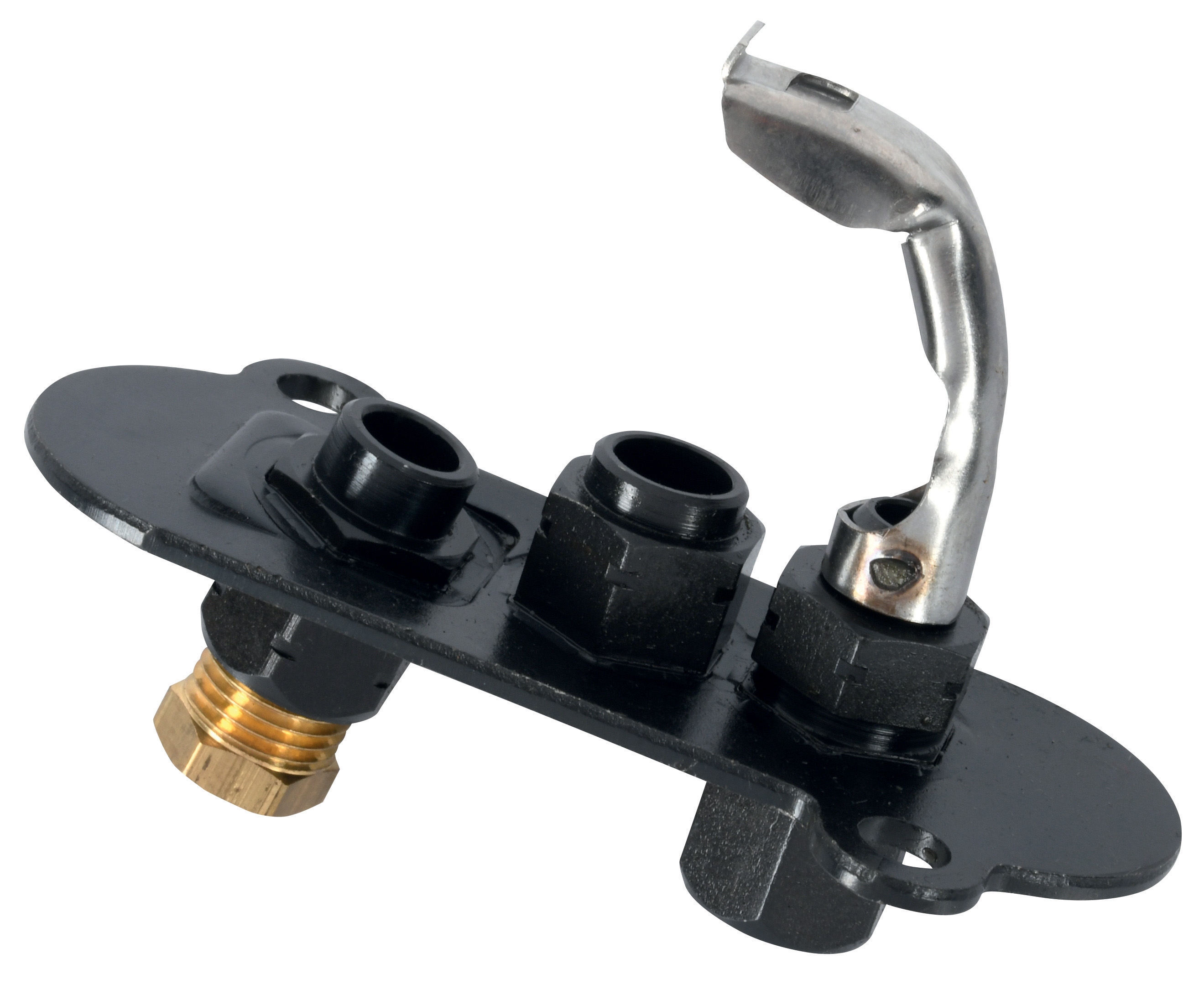
Pilot Light Selection and Function:
Pilot lights serve two critical Controls & Safety roles: they ignite main fuel and provide a continuous flame signal that proves the system is ready for operation. The CBM 1-flame pilot light 0.150.082 and CBM Pilot light 1 flame 0140026 are designed for continuous operation in industrial environments.
Plant managers should understand that pilot lights consume fuel continuously—typically 0.5 to 2 gallons per hour depending on design. While this seems wasteful, the pilot flame serves as your primary Controls & Safety sentinel. Modern pilot lights feature:
- Thermocouple Integration: The pilot flame heats a thermocouple, which generates a small DC voltage (typically 20-30mV) that signals the presence of flame
- Flame Shape Stability: Industrial pilot lights use fixed orifices and air shutter designs that produce stable, cool-burning flames resistant to external air disturbances
- Easy Ignition: Most pilot lights ignite with spark igniters or manual matches, providing reliable Controls & Safety startup across diverse environmental conditions
1. Connect pilot light thermocouple directly to relay input terminals
2. Apply 24V DC power to relay coil and measure thermocouple output voltage with multimeter
3. Ignite pilot light manually and verify voltage increases to 15-25mV
4. Install relay contacts in series with main solenoid valve coil circuit
5. Confirm that pilot flame loss causes relay de-energization within 3 seconds
6. Test manual shutoff button to ensure solenoid valve closes immediately
Maintenance and Troubleshooting Controls & Safety Systems
Proper maintenance transforms Controls & Safety investments into long-term reliability assets. Plant managers who implement systematic maintenance protocols typically extend equipment life by 40-60% compared to reactive approaches.
Monthly Maintenance Procedures:
- Visual Inspection: Check all solenoid valve coils for burn marks, cracks, or corrosion. Listen for unusual humming or buzzing that suggests electrical issues.
- Pilot Light Observation: The pilot flame should be blue with a small yellow tip. Excessive yellow coloration indicates contamination; refer the burner for professional cleaning.
- Thermocouple Testing: Using a multimeter in millivolt mode, verify thermocouple generates 20-30mV when pilot flame is burning. Lower readings suggest thermocouple degradation.
- Relay Contact Inspection: If accessible, visually inspect relay contacts for corrosion or pitting. Clean corroded contacts with fine electrical contact cleaner.
- Solenoid Valve Function Test: Manually cycle the main solenoid valve 10 times using your control switch. Listen for crisp clicking sounds; slow or silent response suggests internal wear.
- Pressure Drop Measurement: Install a pressure gauge downstream of the solenoid valve and measure pressure drop during operation. Compare to baseline readings from commissioning. Increases over 20% suggest internal leakage requiring valve replacement.
- Electrical Continuity Check: Disconnect solenoid valve power and measure coil resistance with an ohmmeter. CBM solenoid coils typically show 30-60 ohms depending on voltage rating. Open-circuit or very low readings indicate coil failure.
| Issue | Symptom | Root Cause | Solution |
|-------|---------|-----------|----------|
| Solenoid valve won't open | Burner won't ignite | Low coil voltage, corroded terminals | Check 24V supply, clean connectors, test relay contacts |
| Solenoid valve won't close | Fuel continues flowing despite shutdown command | Internal leakage, stuck valve spool | Replace solenoid valve with CBM VCS 1E25R/25R05NNWL3 |
| Pilot light extinguishes unexpectedly | Frequent shutdowns, safety lockouts | Drafty environment, contaminated pilot orifice | Install windshield, schedule professional cleaning |
| Relay won't de-energize | Burner stays running despite shutdown | Stuck relay contacts, failed thermocouple | Replace relay with CBM Relay CM391.2 30.5 1.2, test thermocouple |
| Slow solenoid response | Delayed fuel flow, poor flame stability | Air in valve cavity, low voltage | Bleed solenoid cavity, verify minimum 22V at coil |
Advanced Troubleshooting for Plant Managers:
When standard diagnostics fail, implement this systematic approach:
1. Isolate the problem: Determine whether the issue is electrical (relay/coil) or mechanical (valve spool/gas flow)
2. Test components independently: Remove the solenoid valve and apply 24V DC directly to the coil—it should click sharply. If no response, the coil is failed.
3. Verify gas supply: Install a pressure gauge at the solenoid valve inlet. Confirm pressure matches specifications (typically 3-5 bar for industrial burners)
4. Check thermocouple continuity: Measure resistance between thermocouple tip and common terminal. Most thermocouples show resistance below 100 ohms; open-circuit indicates failure
5. Document baseline readings: Keep maintenance logs showing coil resistance, thermocouple voltage, and solenoid closing pressure. Trends in these values predict failures before they occur
Implementation Strategy for Plant Managers
Successful Controls & Safety integration requires coordinated planning. Plant managers should approach implementation in phases:
Phase 1: Audit Current Systems (Weeks 1-2)
Inspect all burners and identify which Controls & Safety components are original equipment, which are replacements, and which are non-standard modifications. This audit forms the baseline for improvement prioritization.
Phase 2: Standardize Components (Weeks 3-8)
Replace obsolete or non-standardized components with industrial-grade equivalents. Using standardized parts from trusted manufacturers like CBM through 3G Electric reduces training requirements and simplifies spare parts inventory.
Phase 3: Document Systems (Weeks 9-12)
Create detailed wiring diagrams, component lists, and maintenance procedures specific to your facility. This documentation is invaluable for training new technicians and troubleshooting emergency situations.
Phase 4: Train Personnel (Weeks 13-16)
Ensure all technicians understand the specific Controls & Safety systems installed in your facility. Include emergency shutdown procedures and basic troubleshooting techniques.
Phase 5: Establish Maintenance Schedule (Ongoing)
Implement the monthly and quarterly procedures outlined above. Tracking these activities demonstrates due diligence if regulatory questions arise.
With over 35 years serving industrial operations globally, 3G Electric understands that Controls & Safety investment protects not just equipment, but personnel safety and operational continuity. Our technical team can assist with component selection, installation support, and ongoing training to ensure your facility maintains world-class safety standards.