Understanding Controls & Safety System Architecture
Controls & Safety systems in industrial equipment represent the critical interface between operational efficiency and worker protection. With over 35 years of experience distributing industrial equipment globally, 3G Electric has witnessed the evolution from mechanical safety systems to sophisticated integrated electronic controls. For maintenance teams, understanding the fundamental architecture of these systems is essential for effective diagnostics and preventive maintenance.
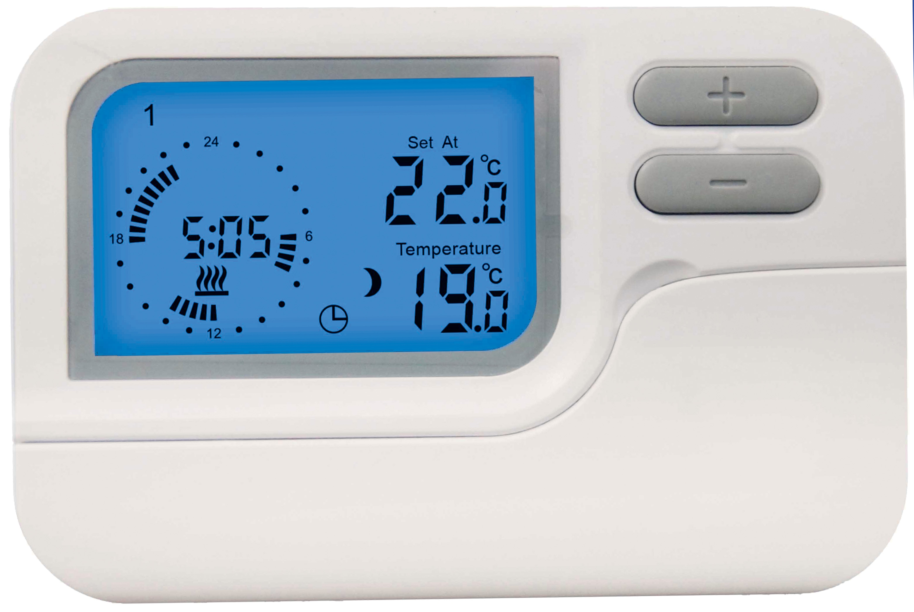
A typical Controls & Safety architecture comprises several interconnected layers: the input stage (sensors and detection devices), the logic stage (controllers and relays), and the output stage (actuators and safety devices). Each layer must function flawlessly to ensure safe operation. The input stage captures real-time conditions through flame detection sensors, temperature monitors, and pressure switches. The logic stage processes this information and makes instantaneous decisions about system operation. The output stage executes these decisions through solenoid valves, pilot lights, and other actuators.
The critical distinction in Controls & Safety design is the difference between control functions (which optimize performance) and safety functions (which prevent hazardous conditions). Safety functions must operate independently of control functions and must fail to a safe state if any component fails. This redundancy requirement drives the selection of specific components designed specifically for safety-critical applications.
Maintenance teams must recognize that Controls & Safety systems are not modular in the traditional sense. A component failure in the input stage can cascade through the entire system, causing unexpected shutdown or, worse, preventing the system from shutting down when required. This reality demands systematic testing protocols and component-level understanding.
Component Selection and Maintenance Protocols
Selecting the correct components for Controls & Safety systems requires understanding both specification requirements and real-world operational conditions. The foundation of any safety system lies in its solenoid valves, which must respond instantly to control signals. The CBM VCS 1E25R/25R05NNWL3/PPPP/PPPP double solenoid valve represents the advanced standard for dual-channel safety applications, providing redundant shutoff capability in critical service conditions.
Double solenoid valves serve as the primary safety boundary in many industrial systems. They offer several advantages over single-solenoid designs: redundant shutoff paths, proven reliability through diversified design, and the ability to achieve higher safety integrity levels (SIL ratings). When maintaining these valves, inspection protocols must verify both coil resistance and armature movement independently. Coil resistance should match manufacturer specifications within 5%, and armature movement should occur smoothly without sticking or hesitation.
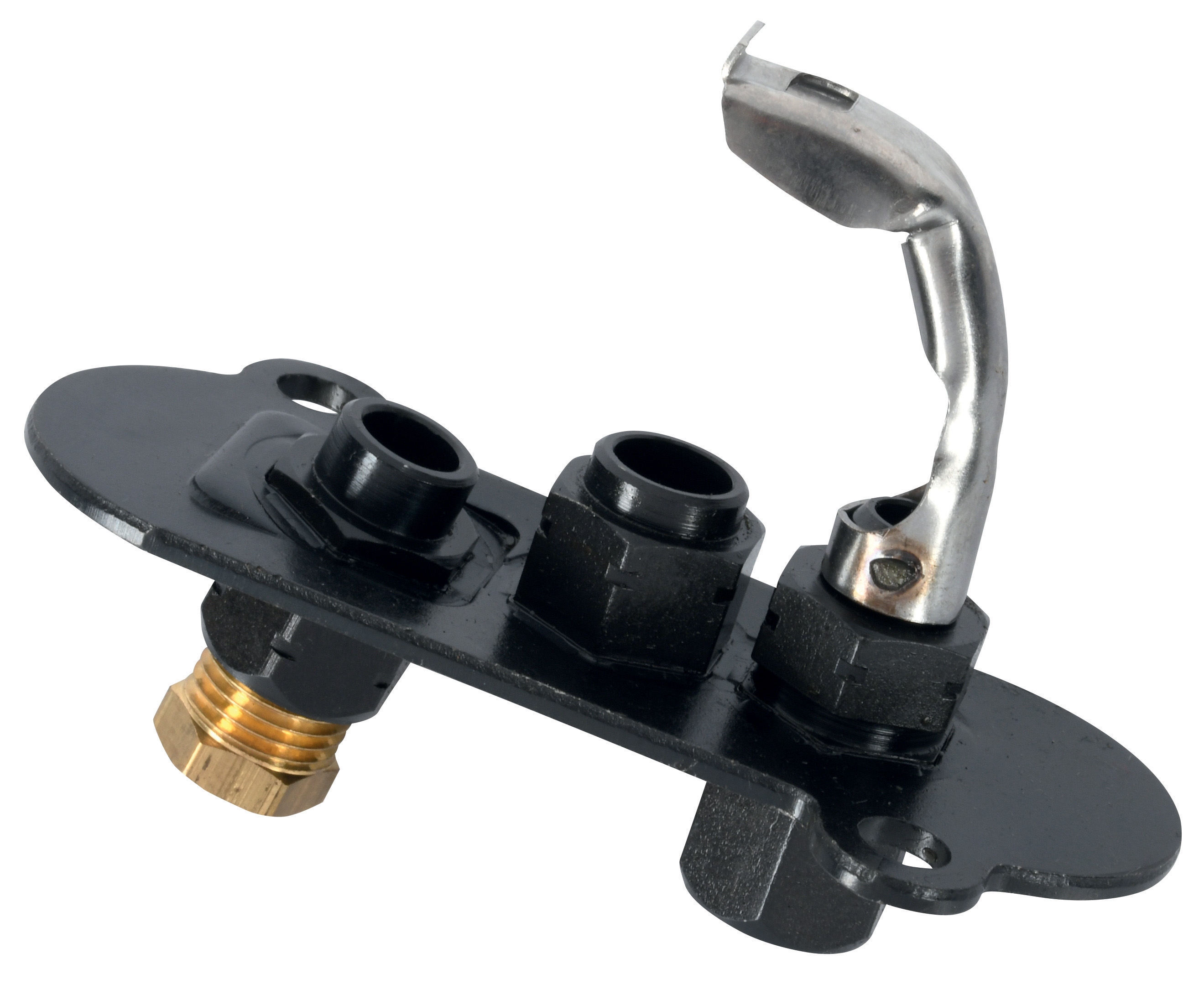
Pilot light systems form another critical safety component, providing visual confirmation of system operation status. The CBM 1-flame pilot light 0.150.082 and CBM Pilot light 1 flame 0140026 serve different application requirements based on pressure drop, flow capacity, and ignition characteristics. Maintenance protocols for pilot lights must include:
- Weekly visual inspection for flame stability and color consistency
- Monthly verification of ignition response time (typically 3-5 seconds maximum)
- Quarterly cleaning of burner ports to eliminate carbon buildup that impairs ignition
- Semi-annual replacement of pilot light assemblies in high-utilization systems
The flame color provides critical diagnostic information. A blue flame indicates proper combustion with adequate air mixture, while yellow or orange flames suggest incomplete combustion or air starvation, requiring immediate investigation.
Control relays and bases form the logic layer of Controls & Safety systems. The CBM Relay CM391.2 30.5 1.2 paired with the CBM Base LGK AGM17 creates a robust control platform for safety-critical logic functions. These components require systematic maintenance including:
- Visual inspection for signs of overheating, corrosion, or moisture intrusion
- Contact resistance measurement to ensure switching performance
- Response time verification through functional testing
- Periodic cleaning of electrical contacts to maintain conductivity
Maintenance teams should establish a component lifecycle management system tracking installation dates, operational hours, and performance history. Most safety-critical components require replacement at manufacturer-recommended intervals regardless of apparent functionality, as degradation is often invisible until catastrophic failure occurs.
Troubleshooting Strategies for Controls & Safety Systems
Systematic troubleshooting of Controls & Safety systems requires a methodical approach that isolates problems to specific functional layers before proceeding to component-level diagnosis. The most common maintenance error is attempting to repair components without understanding the overall system architecture, often resulting in safety function compromise.
Initial troubleshooting must always begin with safety assessment. Determine whether the system is stuck in a safe state (shutdown) or an unsafe state (continued operation with degraded safety function). A system in safe-state failure can continue operation under manual control while repairs proceed. A system in unsafe-state failure requires immediate shutdown of all operations and implementation of alternative safety measures.
For input-stage failures, verify sensor functionality independent of control logic. Flame detection sensors can be tested by temporarily interrupting the pilot flame and confirming system response. Temperature sensors should be verified against known reference temperatures. Pressure switches require static pressure application using a calibrated pressure source. These tests confirm whether the sensor is transmitting accurate signals to the control logic.
Logic-stage failures typically manifest as delayed responses or failure to execute switching functions. Test all relay contacts under load using a load bank or actual control circuit. A relay that switches correctly under no-load conditions may fail when required to carry control current, indicating contact degradation. Time response testing is critical—safety system logic must execute within defined time windows, typically 200-500 milliseconds for most applications.
Output-stage failures include solenoid valve sticking, pilot light ignition failure, or actuator response delay. Solenoid valves should be tested for manual operation before electrical testing, confirming mechanical function is not compromised by scale buildup or corrosion. Electrical solenoid testing requires measuring coil voltage, current, and resistance. A solenoid drawing excessive current often indicates mechanical binding; low current may indicate open windings or poor connections.
Documenting troubleshooting results in a systematic maintenance log enables pattern recognition. If a specific component fails repeatedly, root cause analysis may reveal environmental factors (temperature extremes, vibration, humidity) that demand corrective action beyond simple component replacement.
Preventive Maintenance and System Optimization
Controls & Safety systems deliver their greatest value through preventive maintenance protocols that eliminate failures before they occur. Drawing on 35 years of global equipment distribution experience, 3G Electric recommends a structured maintenance schedule aligned with manufacturer specifications and industry standards.
Daily operator checks form the foundation of preventive maintenance. Operators should verify pilot flame presence and color, confirm audible/visual alarm function, and observe control response during normal operation. These simple checks catch developing problems before they become safety incidents. Operators must be trained to recognize abnormal system behavior and escalate concerns immediately.
Weekly maintenance performed by technicians should include comprehensive visual inspection of all exposed components, verification of solenoid valve operation through manual actuation, and functional testing of safety interlocks. Weekly inspections identify moisture accumulation, corrosion initiation, or mechanical stress before these conditions compromise functionality.
Monthly testing must verify the complete safety logic chain. This includes blocking pilot flame and confirming system shutdown, introducing fault conditions to verify alarm response, and testing all manual override functions. Monthly testing ensures that safety functions remain independent of control functions and will execute properly during actual emergency conditions.
Quarterly maintenance addresses component degradation that occurs gradually over time. Solenoid valve coils require measurement for resistance drift indicating winding degradation. Relay contacts require cleaning to remove oxidation and corrosion. Pilot light burner ports require carbon removal to maintain ignition reliability. Connector contacts throughout the control circuit require cleaning and re-seating to restore full conductivity.
Semi-annual component replacement programs are essential for safety-critical components in demanding service. Pilot light assemblies, solenoid valve coils, relay contacts, and electrical connectors should be replaced at manufacturer-recommended intervals. This preventive replacement strategy eliminates the risk of age-related failure in critical safety functions.
System documentation represents an often-overlooked but critical element of effective maintenance. Maintain comprehensive records including original equipment specifications, all modifications or upgrades, maintenance history, component replacement logs, and performance test results. This documentation enables rapid diagnosis when problems occur and provides the foundation for continuous improvement of system performance and safety.
Regulatory compliance requires that all Controls & Safety system maintenance activities be performed according to documented procedures and by qualified personnel. Maintenance teams should maintain certifications in electrical safety, gas safety systems, and equipment-specific technical skills. Regular training updates ensure that maintenance practices remain aligned with evolving standards and manufacturer recommendations.
Performance Monitoring and Safety Integrity Assessment
Modern Controls & Safety systems must be evaluated not only for immediate functionality but for their safety integrity level (SIL) rating, which quantifies the probability of failure on demand. Maintenance activities directly impact whether a system maintains its designed SIL rating throughout its operational life.
Safety integrity assessment begins with understanding the failure modes of each component and the consequences of those failures. A solenoid valve failure that prevents fuel shutoff during an emergency represents a critical failure with serious consequences. The same solenoid valve failure that prevents fuel supply during normal operation represents a safe failure with minimal consequence. Maintenance procedures must distinguish between these failure modes.
Proof testing—systematic verification that all safety functions work correctly under simulated failure conditions—is the primary maintenance activity that maintains safety integrity. Proof testing must be performed at intervals defined by safety standards (typically annual or biennial for most industrial systems) and must cover all safety functions and their combinations.
Condition monitoring technologies including thermography, vibration analysis, and electrical parameter trending provide early warning of developing component failures. Thermographic inspection can identify excessive solenoid coil heating indicating impending winding failure. Vibration analysis can detect solenoid armature sticking or mechanical binding. Electrical current trending can identify contact degradation in relays before failure occurs.
When proof testing or condition monitoring reveals a safety function approaching its failure threshold, component replacement must be scheduled immediately. Continued operation with degraded safety function violates not only manufacturer recommendations but regulatory requirements in most jurisdictions.
Final safety assessment requires verification that the entire system maintains its designed response characteristics. System response time—the elapsed time from fault detection to complete fuel shutoff—is typically required to be less than one second. Slower response times may require design modification or increased safety monitoring. Annual response time verification using calibrated instruments confirms this critical parameter remains within specification.
Maintenance teams should view Controls & Safety system care not as a burden but as the primary activity that enables safe, reliable operation. Systems that receive comprehensive preventive maintenance deliver decades of reliable service with minimal emergency repairs. Systems that receive only reactive maintenance based on failure events eventually suffer catastrophic failures that disrupt operations and threaten personnel safety. The choice between these outcomes rests fundamentally with maintenance team commitment to systematic, documented preventive care.