Understanding Controls & Safety System Architecture in Your Maintenance Role
Controls & Safety systems in industrial burners represent one of the most critical yet frequently neglected aspects of equipment maintenance. As a maintenance team member, you're responsible for keeping these systems functioning reliably—a responsibility that directly impacts both operational continuity and facility safety.
The Controls & Safety ecosystem in modern industrial burners comprises several interconnected subsystems: solenoid valve control circuits, pilot light ignition systems, relay logic networks, and flame detection feedback loops. Each component serves a specific function within the safety chain, and failure of any single element can trigger a cascade of problems.
With 35+ years of experience distributing industrial equipment globally, 3G Electric has observed that approximately 60% of burner-related shutdowns stem from Controls & Safety component degradation rather than primary burner failure. This pattern reveals a critical insight: preventive maintenance focused specifically on controls and safety systems delivers significantly higher ROI than general equipment servicing.
Understanding your system's architecture is the foundation of effective maintenance. Most industrial burners operate through a sequence: pilot ignition → flame detection → main valve solenoid activation → burner operation → continuous monitoring → safety shutdown. Each transition point depends on Controls & Safety components functioning within specification.
Diagnostic Inspection: Identifying Degradation Before Failure
Practical maintenance begins with systematic diagnostic inspection. Unlike mechanical failures that often produce obvious symptoms, Controls & Safety degradation typically occurs silently until complete failure occurs.
Solenoid Valve Assessment
Double solenoid valves like the CBM VCS 1E25R/25R05NNWL3/PPPP/PPPP control both pilot gas supply and main burner gas flow. During routine inspection, evaluate these indicators:
Electrical continuity testing: Use a multimeter to verify coil resistance at both solenoids. CBM VCS valves typically exhibit 12-15 ohms per coil at 20°C. Resistance values exceeding 20 ohms suggest coil degradation; values below 8 ohms indicate possible shorted windings. Document baseline readings during initial system commissioning—deviations of more than ±2 ohms warrant replacement scheduling.
Acoustic response verification: Apply 24VDC to the solenoid and listen for a distinct clicking sound indicating armature engagement. Absence of sound despite electrical continuity suggests mechanical binding or coil failure. This 10-second test provides immediate feedback on solenoid health without dismantling equipment.
Pressure differential examination: Most solenoid valve failures result from inadequate pressure differential across the valve. Verify upstream pressure meets manufacturer specifications (typically 0.5-3 bar above downstream pressure). Insufficient differential prevents the solenoid from fully opening, causing incomplete combustion and system cycling issues.
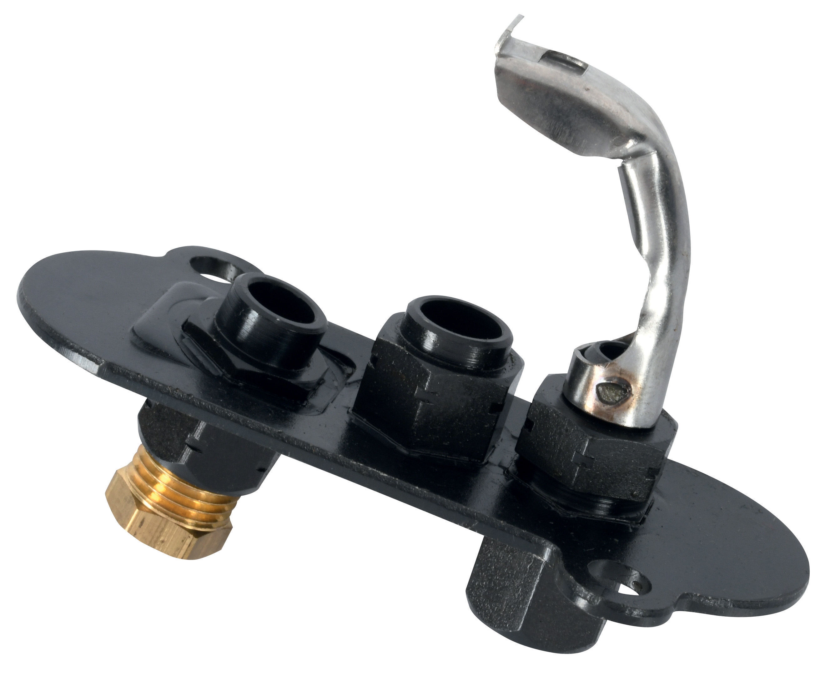
Pilot Light Component Evaluation
Pilot light systems, whether using the CBM 1-flame pilot light 0.150.082 or CBM Pilot light 1 flame 0140026, represent the ignition pathway for your entire burner system. Visual inspection of pilot flame characteristics provides diagnostic information:
Flame color and stability: A healthy pilot flame appears blue with minimal yellow. Persistent yellow indicates incomplete combustion, typically caused by carbon buildup or inadequate air supply. Flame flickering or drooping suggests gas pressure inconsistency or electrode degradation.
Ignition electrode inspection: Visual examination of the electrode tip should reveal minimal carbon accumulation. Excessive black deposits require electrode cleaning using 600-grit abrasive paper. However, if cleaning fails to restore reliable ignition after 2-3 attempts, replacement is more cost-effective than repeated service calls.
Spark gap measurement: Maintain a 3-4mm gap between ignition electrode and ground. Use a feeler gauge to verify spacing after any electrode cleaning or repositioning. Gaps exceeding 5mm dramatically reduce ignition reliability, particularly in humid environments.
Relay Logic and Control Circuit Maintenance
Relay systems, including components like the CBM Relay CM391.2 30.5 1.2 and its CBM Base LGK AGM17, orchestrate the timed sequence of valve operations. These electromechanical devices require specific maintenance approaches.
Contact Inspection and Cleaning
Relay contacts operate thousands of times daily. Each contact transition creates micro-arcing that gradually erodes contact surfaces. Over 12-18 months, accumulated contact degradation causes failure:
Visual contact examination: Remove the relay from the base and visually inspect contacts. Pitting—small craters in the contact surface—accelerates current leakage. Light surface discoloration is normal; significant pitting or melting indicates replacement necessity. Document contact appearance during initial inspection to establish baseline degradation rates.
Contact resistance measurement: Connect a multimeter across closed contacts in resistance mode. New relays typically exhibit <0.1 ohms contact resistance. Resistance readings exceeding 0.5 ohms significantly increase voltage drop across the relay, potentially preventing downstream solenoid energization. This measurement often reveals problematic relays before complete failure occurs.
Cleaning protocol: For relays with visible oxidation but acceptable resistance, contact cleaning extends operational life 6-12 months. Deactivate the relay electrically, then carefully scrub contacts with a small artist's brush and electronics-grade isopropyl alcohol. Do not use sandpaper or files that remove contact plating. Allow 10 minutes air-drying before reinstalling.
Relay Base and Socket Assessment
The relay base socket like the CBM Base LGK AGM17 provides electrical connection and mechanical positioning. Socket degradation causes intermittent relay failures—the most dangerous failure mode:
Insertion resistance testing: With the relay inserted in the base, measure contact resistance at socket connection points. Readings should be nearly identical to direct relay contact measurements (within 0.05 ohms). Significant increases indicate socket degradation. In troubleshooting intermittent shutdowns, socket replacement often resolves issues where relay replacement has failed.
Visual socket inspection: Look for corrosion, burn marks, or discolored pins. Minor tarnishing can be cleaned with fine phosphor bronze brush; severe corrosion requires socket replacement. Test socket security—proper seating is essential. Many intermittent failures result from relays partially seated in degraded sockets.
Preventive Maintenance Scheduling and Troubleshooting Integration
Systematic maintenance scheduling transforms Controls & Safety components from failure-prone elements to predictable, manageable assets.
Recommended Service Intervals
Monthly visual inspection: Examine pilot flame, check solenoid coil resistance, inspect relay contacts visually. This 15-minute procedure identifies 70% of developing problems before they cause shutdowns.
Quarterly detailed diagnostic: Comprehensive testing of all solenoid coil resistances, relay contact resistance, socket inspection, and pressure verification. Create a maintenance log documenting all measurements for trend analysis.
Biannual component replacement: Depending on operational hours and environment, plan replacement of combustion air filters, pilot electrode cleaning, and relay contact rejuvenation. In corrosive or high-vibration environments, advance schedules by 25-50%.
Annual full system calibration: With the burner shut down, verify all control sequences function correctly, test flame detection response time, confirm safety shutdown operates properly, and document complete system performance baseline.
Troubleshooting Methodology for Maintenance Teams
When Controls & Safety systems malfunction, systematic troubleshooting prevents wasted component replacement:
Symptom: Pilot won't ignite
Sequential testing: (1) Verify 24VDC at ignition electrode; (2) Measure spark gap; (3) Confirm gas supply to pilot at solenoid inlet; (4) Test pilot solenoid coil resistance; (5) If resistance normal but no gas flow, solenoid requires replacement; (6) If no voltage reaches electrode despite relay output showing power, check relay base socket connection.
Symptom: Main burner won't fire after pilot ignition
Test sequence: (1) Confirm pilot flame is bright and stable (flame detection depends on proper pilot); (2) Measure flame detector feedback voltage (typically 3-12VDC for photo-resistive sensors); (3) If feedback voltage is low or zero, pilot flame is insufficient; (4) Verify main solenoid receives 24VDC from control circuit; (5) Test main solenoid coil resistance; (6) If voltage is absent, trace relay logic and contact sequence.
Symptom: Frequent shutdown or cycling
Diagnostic approach: (1) Review flame detection stability by observing detector voltage fluctuation; (2) If voltage oscillates or drifts, clean detector lens and check pilot flame stability; (3) Verify all connections in feedback loop are clean and tight; (4) Measure solenoid coil temperature—excessive heat indicates electrical resistance issues; (5) Check fuel supply pressure stability; (6) If problem persists, check relay contact resistance and base socket security.
Implementing Maintenance Documentation and Knowledge Transfer
Effective Controls & Safety maintenance requires documentation that outlives individual team members. Establish a system recording baseline measurements, service dates, and all diagnostic findings.
Create component-specific cards for each solenoid valve, relay, and detector. Record manufacturer specification ranges and your system's baseline measurements. When measurements deviate from baseline, this documentation enables confident decisions about replacement timing rather than guessing.
Maintenance teams benefit from manufacturer technical bulletins. CBM components, like those supplied by 3G Electric, typically include detailed specification sheets documenting acceptable resistance ranges, pressure ratings, and troubleshooting flowcharts. Reference these during inspections and include relevant sections in your maintenance procedures.
With consistent application of these diagnostic procedures and maintenance intervals, Controls & Safety systems transition from mysterious black boxes to manageable, predictable components. Your systematic approach to inspection, measurement, and timely component replacement directly impacts facility safety, operational reliability, and maintenance budget efficiency.
