Controls & Safety Systems: Design Principles and Component Selection Guide for Industrial Burners in Southeast Asia
Industrial burner control and safety systems represent one of the most critical infrastructure investments for manufacturing, heating, and combustion facilities across Southeast Asia. Unlike reactive maintenance or compliance-driven upgrades, strategic system design directly impacts operational efficiency, worker safety, regulatory standing, and total cost of ownership. This comprehensive guide walks procurement and purchase engineers through the foundational principles of controls and safety architecture, enabling informed decisions during equipment selection, integration planning, and troubleshooting phases. Whether you're designing a new installation, retrofitting legacy systems, or scaling operations across multiple facilities, understanding how pressure switches, flame detection cells, relay modules, and gas control blocks work together—and why specific design choices matter—is essential for long-term reliability and safety.
Core Design Principles for Industrial Burner Control Systems
Modern burner control and safety systems operate on a hierarchical principle: multiple independent safety layers, each capable of shutting down the burner independently, prevent dangerous conditions such as unburned gas accumulation, flame loss during operation, or excess pressure in combustion chambers. This redundancy is not optional—it's mandated by international standards including EN 746-2 (safety of gas burners), EN 676 (controls and safety devices), and EN 1854 (pressure switches for gas appliances). Understanding this layered approach is fundamental to system design.
The first layer is pre-ignition safety: before any fuel enters the combustion chamber, the control system must verify that air passages are clear, fan operation is confirmed (if applicable), and purge cycles are complete. The second layer is ignition and flame establishment: once fuel is introduced, the ignition source must reliably ignite the fuel within a specified timeframe (typically 3-5 seconds), and the flame must be detected immediately. If ignition fails or flame detection fails, the fuel valve must close automatically within milliseconds. The third layer is continuous flame monitoring: during operation, the flame must be continuously monitored, and if flame loss is detected, fuel must be shut off and a lockout condition initiated (requiring manual reset). The fourth layer is pressure and flow monitoring: abnormal pressure conditions—whether excessive gas pressure, insufficient air pressure, or loss of combustion air—must trigger immediate shutdown.
Each of these layers requires specific components working in concert. Pressure switches monitor system pressures. Flame detection cells (ionization or ultraviolet) verify flame presence. Electronic relay modules orchestrate timing sequences and logic decisions. Gas control blocks (solenoid valves, regulators, pilot lights) implement the physical shutoff or fuel modulation commands. The design principle is simple: no single component failure should allow hazardous conditions. If a pressure switch fails to a "safe" state (normally closed), the system fails safely. If a flame detection cell provides false signals, a second independent flame detection method or extended proof-of-flame time prevents misoperation.
Technical Architecture: Pressure Monitoring and Sensing Strategy
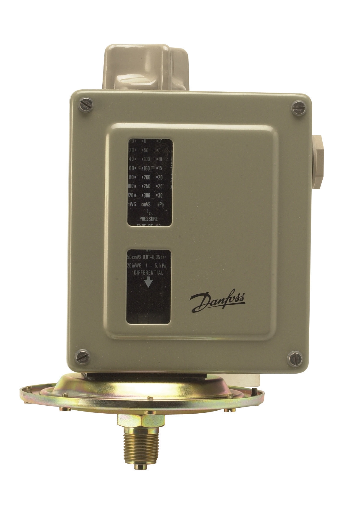
Pressure switches form the backbone of burner safety monitoring. In Southeast Asian industrial facilities operating across tropical climates with humidity levels frequently exceeding 80%, pressure switch selection and installation require particular attention. The Danfoss Pressure Switch RT 5 series exemplifies the diversity of pressure monitoring requirements: this unit offers multiple pressure range variants (from 0.1 bar to 30 bar across different models) and employs unipolar changeover contacts that toggle electrical circuits based on pressure thresholds. A facility might use the RT113 variant (0 to 0.3 bar range) to monitor combustion air pressure in induced-draft systems, while the RT117 variant (10 to 30 bar) monitors gas supply pressure at the burner inlet.
For critical industrial combustion applications requiring certified Safety Integrity Level (SIL) ratings, the Kromschroder Pressure Switch DG 50U/6 represents the highest-specification option. Rated SIL 3 and Performance Level e, this pressure switch meets EN 1854, FM, UL, AGA, and GOST-TR certifications simultaneously—essential credentials for facilities operating across multiple Southeast Asian jurisdictions or exporting products to global markets. The internal locking mechanism prevents pressure drift from causing unintended switching during normal pressure oscillations, a critical feature in high-vibration industrial environments.
Design strategy for pressure monitoring typically follows this pattern: (1) gas supply pressure monitoring at burner inlet (high-pressure switch to detect overpressure, low-pressure switch to detect supply interruption); (2) air/combustion pressure monitoring (low-pressure switch to verify air fan operation and adequate draft); (3) differential pressure monitoring (to detect blockages in fuel lines or air paths). The actual thresholds are application-specific—a low-pressure gas burner for a domestic boiler might use 0.05 bar switches, while an industrial process burner might require 5-10 bar switches. Selecting the correct pressure range for each application prevents false lockouts while ensuring genuine faults are caught immediately.
Flame Detection Integration and Monitoring Cell Selection
Flame detection cells represent the sensory system of burner controls—they "see" or "feel" the flame and report its presence to the control relay. Two primary technologies dominate industrial applications: ionization sensing and ultraviolet (UV) sensing. Ionization detects the electrical conductivity of the flame itself (a gas flame contains free ions that conduct electricity), while UV cells detect the ultraviolet radiation emitted by the flame.
The Siemens Cell QRB4B-B050B70A represents a specialized UV flame monitoring solution for yellow-flame oil burners operating in intermittent duty cycles. This two-wire thermoplastic-jacketed cell provides normal or high response sensitivity options, allowing tuning to specific combustion conditions and burner geometries. In tropical Southeast Asian climates where humidity and salt spray corrosion accelerate electrode degradation, UV cells often outperform ionization cells due to their non-contact sensing principle—there's no electrode exposed to corrosive combustion byproducts or carbon fouling. The QRB4 mounting variants (with or without AGK42 flange, with optional soft plastic sleeve) facilitate installation flexibility across different burner frame sizes and configuration constraints.
For atmospheric and fan-assisted gas burners operating intermittently, the Brahma Relay CM 31 TW30/TS10 combines integrated ionization flame monitoring with solid-state electronic logic and two independent safety contacts in series on the gas valve output. This dual-contact design ensures that a single contact failure cannot cause hazardous valve opening—both contacts must be energized simultaneously for fuel delivery. The auxiliary contact allows independent control of pilot ignition or main gas valve modulation, enabling complex startup sequences where pilot flame is established first, verified, then main burner fuel is released.
Integration strategy requires matching the flame detection method to the burner type and fuel: gas burners with stable, blue-flame combustion suit ionization detection; oil burners with yellow-flame characteristics suit UV detection; dual-fuel burners require dual flame detection cells or careful selection of a method that works reliably for both fuel types. Flame cell location is equally critical—the cell must "see" the flame clearly, positioned to avoid flame impingement on the cell window (which causes deposits and signal degradation) while ensuring sufficient signal strength even with partial flame.
Relay Modules and Control Logic: Orchestrating Safe Startup and Shutdown
Electronic relay modules function as the "brain" of burner control systems, executing timed sequences and logic decisions that implement the safety architecture described earlier. For intermittent operation (most common in heating applications), the Brahma Relay CM 31 TW30/TS10 uses solid-state ignition timing, ignition-proving duration, flame monitoring, and lockout logic all integrated in a single housing. When a call for heat arrives, the relay: (1) energizes the air fan (if present) and allows the purge cycle to complete; (2) generates a spark or hot-surface ignition signal; (3) opens the main gas valve after a brief ignition delay; (4) verifies that flame is detected within a specified window (typically 2-5 seconds); (5) continues monitoring flame throughout operation; (6) cuts off fuel immediately if flame is lost; (7) if re-ignition fails or flame is not established, enters a lockout state requiring manual reset.
For more complex burner systems with modulating power requirements, the Kromschroder BCU 570WC1F1U0K1-E supports both direct ignition and intermittent or continuous pilot ignition modes, with optional bus module capability for coordinated multi-burner control and advanced diagnostics. The BCU 570 series complies with EN 746-2 and EN 676, designed specifically for unlimited-power modulating burners—systems where fuel flow is continuously adjusted based on load demand rather than simple on-off cycling. The optional bus module enables networked communication with multiple burners, allowing supervisory control systems to coordinate ignition sequences, monitor diagnostic parameters, and log fault history across a facility.
Design considerations when selecting relay modules include: (1) ignition type supported (spark plug, hot-surface, or pilot light); (2) flame detection method compatibility (ionization vs. UV); (3) intermittent vs. continuous operation capability; (4) modulation capability (on-off only vs. proportional control); (5) pilot burner control (intermittent pilot, direct ignition, or main burner only); (6) fault response time and lockout logic; (7) manual reset requirement vs. automatic retry capability. These choices must align with the specific burner design and the facility's operational philosophy—a process heater might require continuous pilot for reliability, while a boiler might use direct ignition to save fuel.
Gas Control Blocks and Valve Integration Strategy
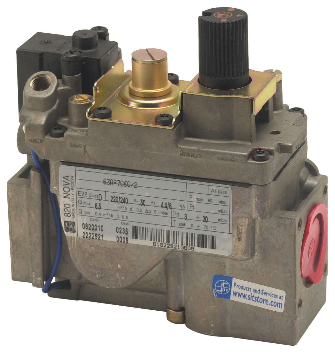
The final physical link in the controls chain is the gas control block—the assembly of solenoid valves, regulators, pilot lights, and pressure gauges that actually controls fuel flow into the burner. The Sit Tandem gas block 0830042 exemplifies the multifunctional integration approach: a single compact module containing two automatic solenoid shut-off valves (Class B), a pressure regulator or flow adjuster, and an adjustable step ignition pin. This tandem configuration provides both redundant fuel shutoff (if one solenoid fails to close, the second provides backup safety) and integrated pressure regulation, eliminating the need for separate regulator installation.
The Sit Tandem specifications illustrate sizing requirements: it handles 4.8 m³/h for Family II gases (natural gas, town gas) and 6.2 kg/h for Family III gases (liquefied petroleum gas, propane), with minimal 5 mbar pressure drop. These flow ratings directly determine the maximum burner power that can be served—a 200 kW gas burner would require a different (larger) gas control block. Pressure drop is critical because excessive drop starves the burner of fuel, reducing flame stability and efficiency, while insufficient regulation (excessive inlet pressure) creates overpressure conditions.
For applications requiring modulating (proportional) control rather than simple on-off operation, the Honeywell Gas block VK 4105 C 1041 U provides electric modulating pressure regulation. This unit features M8×1 pilot connection and M5 threaded pressure feedback, enabling the control system to adjust regulator pressure in response to load signals (typically 4-20mA signals from a temperature controller or burner management system). Modulating control achieves superior fuel efficiency by eliminating overshooting (excess fuel followed by sudden cutoff) and maintaining precise flame conditions across varying load conditions—essential for processes requiring tight temperature control.
Integration strategy requires sizing the gas control block to the specific burner capacity, verifying that pressure drop characteristics don't exceed the control system's ability to maintain stable flame at minimum and maximum firing rates, and ensuring that solenoid valve response time (typically 100-200 milliseconds) allows the control relay sufficient time to verify flame establishment before considering ignition "failed."
Selection Criteria and Design Decision Framework
When designing or upgrading controls and safety systems, procurement engineers should follow a structured decision process:
Step 1: Define Operational Requirements
Determine: (1) Burner type (atmospheric, forced-draft, or induced-draft); (2) Fuel type (gas, oil, or dual-fuel); (3) Operating mode (intermittent or continuous); (4) Power range (kW ratings); (5) Modulation requirements (on-off or proportional control); (6) Geographic deployment (tropical Southeast Asia requires corrosion resistance).
Step 2: Establish Safety Standards and Certifications
Confirm regulatory requirements: Which standards apply to the application (EN 746-2 for gas burners, EN 676 for controls, EN 1854 for pressure switches)? Are SIL ratings or Performance Level certifications required? Which geographic certifications matter (CE for EU export, FM/UL for North American markets, local approvals for ASEAN facilities)? The Kromschroder Pressure Switch DG 50U/6 with SIL 3/PL e certification provides insurance against over-specification, while simpler applications using Danfoss Pressure Switch RT 5 reduce cost without sacrificing safety when SIL certification is not required.
Step 3: Select Pressure Monitoring Strategy
Identify all pressure points requiring monitoring: gas supply, combustion air, differential pressure across fuel filters or air paths. Choose pressure switch models with appropriate range and response characteristics for each application. Account for tropical humidity and thermal cycling—stainless steel wetted parts resist corrosion better than plain steel.
Step 4: Specify Flame Detection Method
Select ionization or UV detection based on fuel type, burner geometry, and environmental factors. Verify that the control relay supports your chosen detection method. Account for cell replacement access—ensure mounting locations allow periodic cleaning and replacement without major disassembly.
Step 5: Design Control Logic and Interlocks
Map out the startup sequence, safety interlocks, and fault response. Sketch the electrical schematic showing how pressure switches, flame cells, manual controls, and the relay module interconnect. Ensure that no single component failure creates a hazardous condition. Plan for manual reset of lockout states—decide whether automatic retry is acceptable or if manual intervention is required.
Step 6: Size Gas Control Components
Select solenoid valves and regulators sized to the burner's maximum and minimum fuel flow requirements. Verify pressure regulation characteristics support stable flame across the operating range. Account for pressure drop in pilot lines and pressure feedback sensing connections.
Step 7: Plan Installation and Commissioning
Design the physical layout of pressure switches, flame cells, gas control blocks, and relay modules. Account for environmental factors (humidity, temperature extremes, vibration) when selecting mounting locations and protective enclosures. Plan for pressure gauge installation to allow technicians to verify pressure settings during commissioning and troubleshooting.
Practical Implementation for Southeast Asian Facilities
Southeast Asian industrial environments present specific challenges: high humidity (60-90%), temperature extremes (ambient 25-35°C, burner combustion zones 800-1200°C), salt spray exposure in coastal areas, and frequent power supply instability. These factors demand attention to material selection and protective design.
For pressure switches, the Danfoss Pressure Switch RT 5 series uses robust construction rated for marine and industrial use, with sealed contact chambers resistant to humidity and corrosion. Mounting these switches inside protective enclosures with desiccant breathers (removable cartridges that absorb moisture) extends service life significantly.
For flame detection cells like the Siemens Cell QRB4B-B050B70A, the two-wire thermoplastic cable jacket provides superior moisture resistance compared to cloth-covered older designs. The optional soft plastic sleeve (QRB4x-xxxxB variant) adds mechanical protection in harsh combustion environments.
For relay modules such as the Brahma Relay CM 31 TW30/TS10, solid-state electronic design (no moving mechanical contacts) provides superior reliability in vibration-prone industrial settings compared to older electromechanical relays. However, electronic circuits are sensitive to voltage fluctuations; installation behind properly rated surge protection and voltage stabilization equipment is essential in regions experiencing frequent power surges.
For gas control blocks, the Sit Tandem gas block 0830042 integrates multiple functions into a sealed assembly, reducing external connections that might collect moisture or corrosion. However, even sealed blocks require protective mounting: overhead installation avoids water pooling, while vibration isolation mounts reduce mechanical stress from pulsing burner operation.
Closing Guidance and Next Steps
Effective controls and safety system design is an engineering discipline combining physics, standards compliance, and practical troubleshooting experience. This guide provides the conceptual framework; successful implementation requires translating principles into specific component selections, electrical schematics, and installation procedures tailored to your facility's unique circumstances.
The products discussed—pressure switches, flame detection cells, relay modules, and gas control blocks from manufacturers like Danfoss, Kromschroder, Siemens, and Sit—represent proven solutions deployed across thousands of industrial installations throughout Southeast Asia. Their technical specifications, certifications, and integration capabilities form the foundation of safe, reliable burner operation.
For assistance selecting the right components for your specific application, evaluating alternatives, or planning integration strategies for your facility, the technical specialists at 3G Electric are available to review your burner specifications, facility requirements, and regulatory constraints. Our team brings three decades of industrial equipment distribution experience throughout Southeast Asia, with deep knowledge of product compatibility, local installation standards, and troubleshooting protocols. Contact 3G Electric today to discuss your controls and safety requirements.