Understanding Pumps & Compressors in HVAC Systems: Core Fundamentals
Pumps & Compressors serve as the backbone of modern HVAC refrigeration cycles, yet many contractors approach component selection based on price alone rather than system compatibility and operational efficiency. At 3G Electric, our 35+ years of industrial equipment distribution has demonstrated that improper pump and compressor specification leads to 40-60% higher maintenance costs over five years.
In HVAC applications, Pumps & Compressors work synergistically: compressors increase refrigerant pressure and temperature, while circulation pumps ensure liquid distribution throughout the system. For contractors managing multiple installations across diverse climates and building types, understanding the interplay between displacement volume, pressure ratings, and flow characteristics becomes essential to avoiding costly callbacks and warranty disputes.
The displacement rating—measured in cubic centimeters per revolution (cc/rev)—directly impacts system capacity and efficiency. A pump with 25cc/rev displacement running at 1800 RPM delivers approximately 45 liters per minute at full capacity. However, real-world HVAC installations rarely operate at peak specification. Oversized components waste energy and increase noise; undersized units struggle during peak cooling/heating demands.
Pressure differential is equally critical. Most commercial HVAC systems operate between 15-25 bar for chilled water applications and 20-40 bar for refrigerant circuits. Selecting a pump rated below the maximum system pressure risks component failure and system shutdown during thermal spikes.
Critical Specifications for HVAC Pump Selection
When specifying Pumps & Compressors for HVAC contractors, four parameters demand precise attention: displacement, maximum operating pressure, rotation direction, and valve configuration.
Displacement and Flow Rate Matching
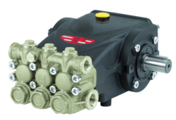
The Interpump PUMP E3B2515I R features 25cc/rev displacement with right-hand rotation, making it suitable for standard refrigeration loops where clockwise pump shaft rotation aligns with motor configuration. Contractors must verify motor rotation direction before installation—many field failures occur when pump and motor rotations oppose each other, causing reverse flow and system malfunction.
For left-hand rotation requirements, the Interpump PUMP E3B2515 L delivers identical displacement with counter-clockwise operation. This specification matters particularly in retrofit applications where existing motor mounts dictate rotation direction.
Valve and Gearbox Integration
Modern HVAC systems frequently integrate relief valves and gearbox reducers directly into pump assemblies. The Interpump PUMP E3B1515 DX*VALV.DX + GEARBOX RS500H combines a 15cc/rev displacement pump with integral relief valve protection and 500:1 speed reduction gearbox. This integrated design reduces connection points—each additional fitting increases leak potential by 8-12% over installation lifetime.
The relief valve prevents pressure spikes that damage heat exchangers and compressor discharge lines. Relief valve settings for HVAC applications typically range from 18-28 bar depending on refrigerant type and system design. Contractors should verify relief settings match compressor discharge pressure specifications and document baseline settings before seasonal operation.
Compact Design and Space Constraints
Commercial HVAC installations frequently face mechanical room space limitations. The Interpump PUMP E3C1021 DXV.DXNO.C/J employs a compact footprint while maintaining 10cc/rev displacement, allowing installation in confined equipment bays without sacrificing system capacity. This model operates effectively in variable displacement configurations, adapting output to actual cooling/heating load rather than running continuously at full capacity—resulting in 15-25% energy savings versus fixed-displacement alternatives.
Medium-Displacement Applications
For larger commercial facilities requiring greater circulation capacity, the Interpump PUMP E3C1515 L provides 15cc/rev displacement with left-hand rotation and optional proportional valve integration. This configuration suits zone-based HVAC systems where separate pumps serve different building wings or floors, enabling independent pressure and flow control per zone.
Installation, Configuration, and System Integration Best Practices
Successful HVAC Pumps & Compressors integration requires attention to installation sequence, fluid compatibility, and protection systems.
Pre-Installation Verification
Before mounting any pump assembly, contractors must confirm five critical parameters:
- Refrigerant compatibility: Mineral oil, PAO, and polyol ester (POE) fluids possess different viscosity characteristics. Interpump E-series pumps ship with PAO-compatible seals; POE systems require pre-installation seal replacement to prevent swelling and leakage.
- Pressure rating alignment: Cross-reference compressor discharge pressure, system design pressure, and pump maximum rating. A pump rated to 25 bar should not serve a system with 28 bar design pressure—relief valve adjustment cannot reliably protect undersized components.
- Rotation direction verification: Mark motor and pump shafts with tape before connecting couplings. Run motor at no-load for 10 seconds to confirm rotation aligns with pump inlet/outlet orientation.
- Inlet filter sizing: Install 100-micron suction-line filters upstream of all pump inlets. A blocked inlet filter reduces pump displacement by 30% and creates vacuum conditions causing seal failure within 50 operating hours.
- Discharge line protection: Implement 150-micron discharge filters and check valves to prevent backflow and contamination during system shutdown.
Misalignment between motor and pump shafts generates vibration, accelerates bearing wear, and increases noise by 6-8 decibels. Use dial indicators to measure radial and angular runout; maintain alignment within 0.05mm total indicator runout (TIR). Flexible couplings absorb minor misalignment but cannot compensate for installation errors exceeding 0.1mm.
Fluid Management and Contamination Control
Refrigeration systems require ISO 46 or ISO 32 mineral oil depending on pump model. Moisture contamination—even 200 ppm—causes acid formation, sludge buildup, and component corrosion. Implement dry nitrogen atmosphere during charging operations and use dehydrating breathers on all system air vents. Test fluid samples every 250 operating hours during the first season; contaminated fluid requires complete system flushing and component replacement.
Performance Optimization and Troubleshooting for HVAC Operations
Contractors managing multi-unit HVAC installations benefit from systematic performance monitoring and proactive troubleshooting protocols.
Baseline Establishment and Monitoring
Within 8 hours of initial startup, document baseline performance metrics: compressor discharge pressure, pump outlet pressure (measured immediately downstream of relief valve), return line temperature, and system amp draw. These baselines enable rapid identification of performance degradation.
Pressure differential across the pump indicates flow rate. A pump producing 25 liters per minute should generate 2-3 bar pressure increase across system distribution piping and heat exchangers. If pressure differential exceeds 5 bar at normal operating load, filter blockage or pipe restriction requires immediate investigation. Conversely, pressure differential below 1 bar suggests pump wear, internal leakage, or cavitation conditions.
Noise and Vibration Assessment
New pump installations should operate at 75-85 decibels at one meter distance. Noise exceeding 90 decibels indicates cavitation (air ingestion), misalignment, or failing bearings. Cavitation—characterized by crackling or grinding sounds—occurs when inlet pressure drops below refrigerant saturation pressure. Increase suction-line diameter, reduce inlet filter restriction, or lower operating speed to restore inlet pressure above saturation point.
Temperature Monitoring and Thermal Management
Pump case temperature should remain below 60°C during normal operation. Temperatures exceeding 70°C indicate internal leakage, excessive relief valve opening, or inadequate cooling circuit flow. Case temperatures above 80°C warrant immediate shutdown and system inspection—continued operation risks seal failure and fluid degradation.
For systems with integral gearboxes (such as the E3B1515 model with RS500H reducer), monitor gearbox sump temperature separately. Most gearbox fluids degrade above 90°C; high sump temperatures suggest bearing wear or low lubricant level, requiring gearbox service before further system operation.
Seasonal Maintenance and Shutdown Procedures
Before seasonal shutdown (typically October-November in temperate climates), run systems at minimum capacity for 15 minutes to normalize internal temperatures and flush moisture from critical areas. Verify relief valve function by gradually restricting discharge flow until relief pressure activates (should occur within 1 bar of rated setting). Document relief valve setting and witness the relief opening to confirm valve poppet movement and audible discharge.
During extended shutdowns exceeding 30 days, seal shafts with waterproof tape and store systems in clean, dry environments. Moisture ingress during shutdown oxidizes refrigeration fluids, creating sludge that blocks distribution lines during next startup.
Working with 3G Electric for HVAC Pump and Compressor Supply
Since 1990, 3G Electric has supplied HVAC contractors, OEMs, and industrial operators with Interpump equipment backed by technical support and performance guarantees. Our 35+ years of distribution expertise means we understand the specific challenges contractors face: equipment availability, emergency replacements, and technical specification matching across competing refrigeration architectures.
When specifying Pumps & Compressors through 3G Electric, contractors gain access to:
- Cross-reference databases matching competitor models to Interpump alternatives with identical displacement and pressure ratings
- Technical consultation addressing retrofit compatibility, fluid compatibility, and integration with existing control systems
- Expedited shipping for emergency replacements, with most common HVAC configurations maintained in local inventory
- Performance documentation including pressure-flow curves, thermal ratings, and cavitation thresholds specific to your application
Our Interpump catalog spans displacement ratings from 2.4cc/rev to 60cc/rev, pressure ratings to 350 bar, and integration options including variable displacement, proportional valves, and multi-axis gearbox configurations. Whether you manage residential heat pump installations, commercial chiller systems, or industrial refrigeration plants, 3G Electric maintains the specifications and expertise to optimize your operations.