Understanding Integrated Maintenance & Service Architecture
Maintenance & Service excellence in modern industrial equipment demands more than reactive repair protocols. With over 35 years of experience as a global industrial equipment distributor, 3G Electric has observed that the most efficient maintenance teams operate through integrated system health monitoring—where pressure systems, combustion components, safety devices, and fluid management work as interconnected diagnostic units.
Traditional maintenance approaches treat each component in isolation: nozzles are serviced separately, burners are inspected independently, and safety systems are checked on fixed schedules. This fragmented approach creates blind spots. When a pressure nozzle begins degrading, related components in the fuel supply chain and combustion system experience compensatory stress. A Maintenance & Service strategy that recognizes these interdependencies reduces unplanned downtime by 30-40% and extends equipment lifecycle significantly.
The foundation of integrated Maintenance & Service begins with understanding your equipment ecosystem. Most industrial heating and pressurized systems contain five critical subsystems: pressure delivery (nozzles and injectors), combustion (burners and ignition), fuel management (reservoirs and pumps), safety controls (alarms and shutoffs), and expansion/pressurization (tanks and inflation systems). Each subsystem generates diagnostic data that informs the health of others.
Subsystem Monitoring Protocols and Cross-System Diagnostics
Pressure Delivery and Combustion System Integration
Flat jet nozzles like the CBM Flat jet nozzle HP 1/4"M BSPT index 25 angle 15° operate at precise pressure specifications, typically 45-100 bar depending on application. These nozzles are engineered to produce specific spray patterns that directly influence burner performance and combustion efficiency. A maintenance team should establish monthly monitoring of nozzle pressure drop—any deviation of more than 5% from baseline indicates internal fouling or wear.
When monitoring nozzle performance, simultaneously track burner spray characteristics. If the FBR BURNER GAS X5/MF TL EL VC LPG shows signs of uneven flame pattern or flame instability, the root cause often traces back to nozzle degradation rather than burner malfunction. This diagnostic insight prevents unnecessary burner replacement and directs maintenance resources to the actual problem.
Implement a cross-system check sequence: inspect nozzle spray pattern visually, measure downstream pressure at the burner inlet, and record flame sensor readings simultaneously. This triangulated data reveals whether pressure loss occurs at the nozzle, in connecting lines, or at the burner head. Documentation of these readings creates a trending database that predicts component failure 2-3 weeks in advance.
Fuel Management System Diagnostics
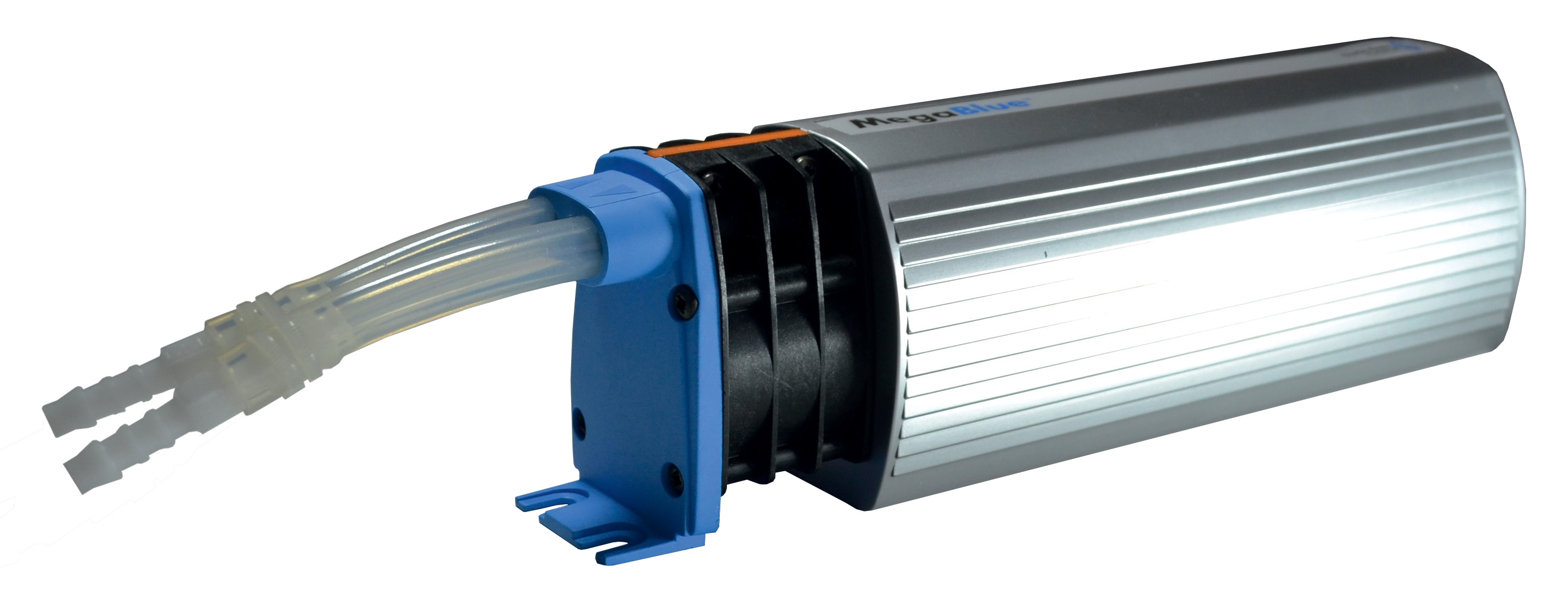
Reservoir health directly impacts the entire fuel delivery chain. The CBM Megablue reservoir alarm + shut-off X87-813 serves as both a safety device and a diagnostic indicator. However, maintenance teams often overlook the diagnostic information it provides. When this alarm system triggers fuel shutoff events, it signals not just a low-fuel condition but potentially indicates fuel consumption anomalies that may reflect burner inefficiency.
Track how frequently the shutdown occurs relative to expected consumption rates. If a system that normally triggers shutdown once weekly suddenly triggers three times weekly, this represents a 200% efficiency loss. The root cause might be:
- Nozzle fouling increasing fuel flow for combustion completeness
- Burner becoming richer due to air inlet degradation
- Flame detection sensor drift causing longer ignition attempts
- Pressure regulation system creep
Regular monitoring of the CBM Expansion tank inflator battery 2000 mAH pressure status provides critical fuel supply stability information. Expansion tanks maintain consistent fuel line pressure as systems heat and cool. A declining charge in the inflation battery signals pressure loss in the tank, which cascades through the fuel system, affecting nozzle spray pattern and burner combustion.
Establish a quarterly tank pressure inspection routine. Record the pre-charge pressure (typically 0.5-0.7 bar for expansion tanks) and the current operating pressure. A 10% pressure loss over three months is normal; anything beyond 15% indicates a slow leak in the tank or its connections. Addressing this before total pressure loss occurs prevents fuel starvation and emergency shutdowns.
Safety System Integration with Operational Diagnostics
Safety devices like alarms and shutoffs should not be viewed solely as emergency backstops. The CBM Megablue reservoir alarm + shut-off X87-813 contains valuable operational intelligence. When this device executes a shutoff, record the context:
- What was the system load when shutdown occurred?
- What was the fuel level at shutdown?
- How many shutoff cycles occurred in the monitoring period?
- What fuel consumption rate was observed before shutdown?
Maintenance teams should implement a "diagnostic interrogation" protocol for each safety event. Rather than simply refilling and restarting, perform a five-minute diagnostic sequence:
1. Pressure System Check: Verify all nozzle pressures match specifications. Compare readings to baseline data (establish baselines during initial installation or after major service)
2. Combustion Verification: Observe flame color and steadiness. Yellow flame indicates incomplete combustion (dirty nozzle or burner); blue flame indicates proper combustion
3. Fuel Flow Rate Assessment: Monitor the time required to consume a known fuel volume. Compare to engineering specifications
4. Air Intake Inspection: Verify burner air inlet screens are clean and unobstructed
5. Sensor Response Testing: Confirm flame sensors respond correctly to combustion changes
This sequence takes minimal time but generates data that predicts failure modes before they cause system downtime.
Preventive Component Lifecycle Management
Every component in an industrial system has a service life measured in operating hours, thermal cycles, or maintenance intervals. Effective Maintenance & Service teams maintain component-level tracking with the following information for each item:
Component Service Record Template:
- Installation date and operating hours at installation
- Current operating hours (updated weekly)
- Inspection interval (hours or months)
- Expected replacement interval
- Last inspection date and findings
- Trending data (pressure readings, fuel consumption, efficiency metrics)
- Next scheduled service date
For pressure nozzles like the CBM Flat jet nozzle HP 1/4"M BSPT index 055 angle 15°, establish replacement at 2,000 operating hours or annually, whichever comes first. However, allow trending data to override this schedule. If pressure drop monitoring shows stable performance at 2,200 hours, extension to 2,500 hours may be justified. Conversely, if pressure drop accelerates at 1,800 hours, replacement should occur immediately.
For modulating burners like the FBR BURNER GAS X5/MF TL EL VC LPG, maintenance intervals vary based on fuel quality and operation hours. Premium burners with optional modulation kits may operate 3,000+ hours between major service. However, in applications with lower fuel quality or continuous operation, service intervals should reduce to 1,500-2,000 hours.
Create a rolling maintenance calendar that staggers component replacement. Rather than replacing multiple components simultaneously (which creates extended downtime and high parts costs), schedule replacements across quarters. This approach maintains system availability while distributing labor and costs evenly.
Real-Time Performance Trending and Predictive Maintenance
The final frontier in Maintenance & Service excellence involves moving from reactive and preventive maintenance to predictive maintenance, where you replace components just before failure occurs—not after they fail and not on arbitrary fixed schedules.
This requires systematic data collection. Establish daily or weekly recording of:
- Fuel consumption rates (gallons or liters per operating hour)
- System pressure readings at critical points
- Combustion efficiency metrics (where available through boiler or furnace instrumentation)
- Flame sensor response times
- Alarm and safety system event logs
- Environmental conditions (outdoor temperature, humidity)
Over 4-6 weeks of operation, patterns emerge. You'll establish baseline performance curves that account for seasonal variations and operational modes. When actual performance deviates from the trend by more than 10%, investigate the cause. This investigation often identifies degrading components before catastrophic failure.
For example, if fuel consumption typically increases 2-3% during winter heating season but suddenly increases 8%, multiple failure modes might be developing:
- Nozzle pressure dropping due to internal fouling
- Burner air inlet becoming partially blocked
- Expansion tank pressure declining, reducing fuel system efficiency
- Combustion chamber becoming fouled with carbon deposits
Investigate systematically, but replacement priorities should be guided by cost-to-replace versus cost-of-failure. Replace the component with the highest failure probability first, then reassess before proceeding to the next replacement.
Maintenance & Service Documentation and Continuous Improvement
No Maintenance & Service strategy survives implementation without systematic documentation. The investment in recording data only yields returns when that data informs decision-making over months and years.
Maintenance teams should establish:
- Equipment Master Files: Complete specifications, installation records, and design operating parameters for each system
- Component History Logs: Service records for every component, especially those replaced during warranty periods (early failures reveal design issues)
- Performance Trend Spreadsheets: Monthly summaries of key metrics allowing visual identification of degradation patterns
- Failure Analysis Reports: When components fail prematurely, document the failure mechanism and contributing factors
- Maintenance Procedure Documents: Step-by-step guides for each service task, continuously refined based on technician feedback
With 35+ years serving industrial equipment users globally, 3G Electric recommends treating documentation as a core maintenance function, not an administrative burden. Teams that document comprehensively reduce repeat failures by 40-60% because institutional knowledge becomes accessible rather than residing in individual technicians' experience.
Implementing integrated Maintenance & Service monitoring transforms maintenance from a cost center into a strategic advantage, extending equipment life, reducing emergency repairs, and improving operational reliability across your industrial systems.