Understanding HVAC Measurement & Detection Systems
HVAC contractors depend on accurate Measurement & Detection equipment to maintain system efficiency, ensure safety compliance, and provide reliable climate control. When these instruments fail or provide inaccurate readings, it creates cascading problems—from improper refrigerant charge levels to undetected gas leaks and unreliable temperature control.
With over 35 years of experience distributing industrial equipment globally, 3G Electric has supported countless HVAC professionals in diagnosing and resolving measurement system failures. This guide provides actionable troubleshooting procedures for the most common Measurement & Detection issues you'll encounter in the field.
Temperature Sensor Failures and Diagnostics
Temperature sensors are critical to HVAC system performance. Whether measuring suction line temperature, discharge air temperature, or evaporator coil conditions, sensor failures lead to incorrect system response and thermal comfort problems.
Common Temperature Measurement Problems
Symptoms indicating sensor failure:
- Inconsistent temperature readings that fluctuate unexpectedly
- Readings that don't match actual conditions you observe
- System cycling on/off excessively without reaching setpoint
- One zone reading correctly while others show drift
- No response to thermostat adjustments
Diagnostic Procedure for Temperature Sensors
1. Verify sensor contact: Remove the surface temperature sensor from its mounting location. Check for dirt, corrosion, or physical damage on the sensing element. Clean with a soft, dry cloth if contamination is present.
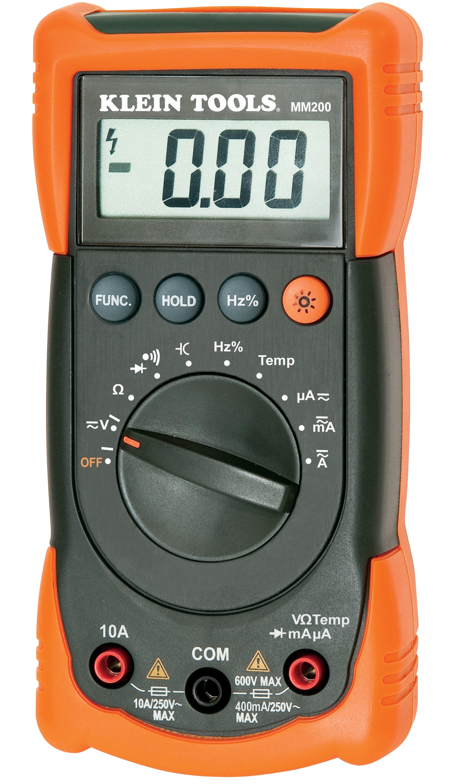
2. Test thermal response: Use the CBM Automatic Multimeter MM420 to measure resistance across the sensor terminals. Record the ohm value and compare against manufacturer specifications for the temperature range you're testing. A digital multimeter allows you to perform continuity testing and resistance measurement simultaneously.
3. Cross-reference with actual conditions: Place the sensor in ice water (32°F/0°C) and boiling water (212°F/100°C) while measuring resistance values. This confirms the sensor's calibration status. Resistance drift of more than 2-3% indicates calibration failure requiring replacement.
4. Check wiring integrity: Loose connections at the sensor terminal or control board cause false readings. Disconnect and reconnect the sensor wire three times, observing for any resistance changes on your multimeter. Consistent values confirm good connections.
5. Evaluate response time: Note how quickly the sensor reading changes when you move it between temperature extremes. Sluggish response (more than 30 seconds) suggests sensor degradation, even if resistance values are acceptable.
When to replace: Surface temperature sensors like the CBM Surface Temperature Sensor TE-SNW-E should be replaced if they show resistance drift outside manufacturer tolerances, fail the ice/boiling water test, or display response times exceeding equipment specifications.
Pressure Measurement Failures and Troubleshooting
Pressure gauges and measurement devices are essential for diagnosing refrigerant charge levels, system blockages, and compressor problems. Inaccurate pressure readings lead to incorrect service decisions and potential equipment damage.
Identifying Pressure Gauge Problems
Signs of pressure measurement failure:
- Gauge needle stuck at one position that doesn't change with system operation
- Erratic needle movement that doesn't correlate with compressor cycling
- Pressure readings that seem impossible (vacuum on high side, extremely low on low side)
- Different readings on two identical gauges connected to the same service port
- Gauge dial fogging or internal moisture visible behind glass
Step-by-Step Pressure Diagnosis
1. Visual inspection: Examine the gauge face for internal fogging, water droplets, or debris. Check the dial for mechanical damage. Look at the gauge mounting point for leaks or corrosion. Any internal contamination requires gauge replacement; these instruments cannot be effectively cleaned.
2. Zero point verification: Before connecting to the system, verify that the gauge reads zero (or the appropriate baseline) with no refrigerant pressure applied. If the needle doesn't return to zero, the gauge mechanism is faulty and must be replaced.
3. Comparative testing: Connect a known-good backup gauge alongside your test gauge at the same service port. Pressure readings should match within ±2 psi (0.14 bar) at steady state. If readings diverge significantly, your primary gauge has lost accuracy.
4. Check isolation valve function: If pressure won't stabilize, the isolating valve on the gauge may be stuck. Carefully open and close the valve 3-4 times while observing pressure response. A stuck valve prevents accurate readings and requires valve replacement or gauge retirement.
5. Assess gauge range appropriateness: Confirm you're using the correct gauge range for the measurement. A low-pressure gauge (0-150 psi) will show minimal needle movement for high-side pressure readings and vice versa. Wrong gauge selection appears as a measurement problem but isn't.
Selecting replacement gauges: The CBM Green ABS Pressure Gauge D63 0/+1bar G1/4 works for low-pressure applications, while the CBM ABS Green Gauge D50 0/+250bar G1/4 handles high-pressure systems. Choose based on your intended application to ensure readable, accurate measurements.
Gas Detection and Electrical Measurement System Troubleshooting
Refrigerant leak detection and electrical system diagnostics are increasingly critical for both safety and regulatory compliance. Modern HVAC systems require reliable gas and electrical measurement capability.
Gas Detection System Failures
Common gas detection issues:
- Detector fails to alarm when refrigerant is deliberately introduced
- False alarms triggered by cleaning products or other airborne chemicals
- Sensor unresponsive after extended shutdown periods
- Multi-zone detection systems where some probes read but others don't
- LED indicators showing power but no gas sensing response
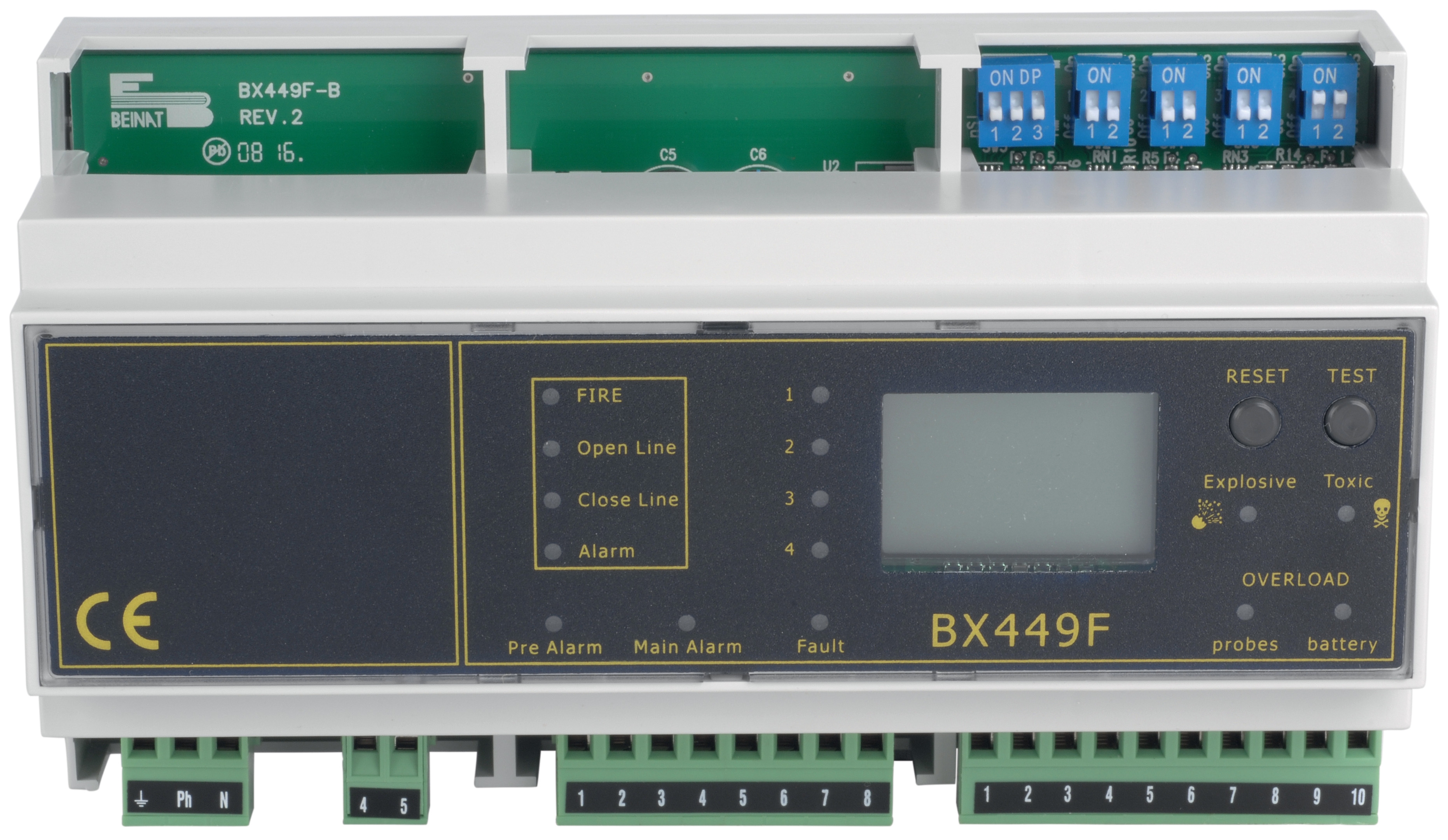
1. Verify power supply: A CBM Gas Detection Center Din Rail 8 Probes - 12V requires stable 12V DC power. Use your multimeter to check voltage at the device terminals. Voltage below 10.5V causes reduced sensor sensitivity.
2. Test individual probe sensors: Disconnect one probe at a time (with power off) and measure resistance at the probe connector. Resistance values should be within the 100-200 ohm range for functioning sensors. Open circuit or near-zero readings indicate probe failure.
3. Validate sensor response: In a safe, controlled environment, introduce a small amount of refrigerant near the sensor intake. Response time should be 5-15 seconds depending on the detection model. Sensors responding in 30+ seconds are degraded and should be replaced.
4. Check calibration certificates: Gas detection sensors require factory calibration verification. Review the equipment documentation to confirm your system was calibrated within the past 12 months. Sensors older than 2 years without recalibration should be professionally tested.
5. Inspect probe placement: Ensure probes are mounted at points where escaping gas would naturally accumulate (low areas for heavier refrigerants). Incorrect placement causes false negatives, appearing as system failure when the problem is installation.
6. Test alarm output circuits: Verify that alarm activation at the detector actually triggers your building notification system. Disconnect the alarm wire and trigger the detector manually while observing whether the alarm relay activates. Failed relay contacts prevent alerts despite proper gas detection.
Electrical Measurement Failures
Symptoms of electrical measurement problems:
- Multimeter readings inconsistent when testing the same point multiple times
- Voltage measurements that don't make sense for the circuit being tested
- Resistance readings that seem too high or low compared to specifications
- Device failing to power on despite correct voltage present
- Intermittent readings that change as you move the test leads
1. Verify meter functionality: Test your CBM Automatic Multimeter MM420 against a known reference. Measure a battery voltage (9V battery should read 8.5-9.5V), check continuity across a known resistor, and verify zero resistance across a direct wire connection. Failed reference tests mean the meter needs replacement or professional calibration.
2. Check probe quality: Worn probe tips or cracked probe insulation causes measurement errors. Inspect probes for physical damage. Clean probe tips with a dry cloth if oxidation or contamination is present.
3. Test continuity properly: For safety testing (checking ground continuity), switch to ohms mode and connect probes directly. Reading should show near-zero ohms for good continuity. Readings above 5 ohms in a ground circuit indicate loose connections requiring repair.
4. Measure voltage accurately: Switch to appropriate voltage range (DC or AC as needed) and connect the black probe to ground or negative, red probe to the test point. Fluctuating readings suggest loose connection at test point or meter probe tip.
5. Validate meter range selection: An automatic meter selects range, but manual meters require correct range selection. Testing 120V AC on a 10V range will show overload error. Select 250V or 600V AC range for typical HVAC control circuit testing.
Preventive Measurement System Maintenance
Regular maintenance extends equipment life and prevents unexpected failures in the field.
Quarterly Maintenance Tasks
- Pressure gauges: Store with isolation valves closed. Inspect quarterly for fogging, damage, or corrosion. Keep in protective case when not in use.
- Temperature sensors: Test response time at least quarterly. Record baseline resistance values for each sensor to track drift over time.
- Gas detectors: Review power supply voltage monthly. Perform functional tests using calibration gas at least every 6 months.
- Digital multimeters: Store in protective case with batteries removed if equipment will be idle for months. Test against reference sources before each major use.
Documentation Recommendations
Maintain a simple log for each piece of Measurement & Detection equipment:
- Purchase date and initial calibration status
- Results of quarterly functionality tests
- Any repairs or component replacements
- Dates of professional calibration services
- Notable failures or unusual readings encountered
This documentation helps identify patterns (such as a specific gauge model's tendency to develop fogging) and demonstrates compliance with industry standards.
Conclusion
Accurate Measurement & Detection is foundational to professional HVAC service. By following these systematic troubleshooting procedures, you can quickly distinguish between true equipment failure and misapplication issues, reducing diagnostic time and improving customer satisfaction.
3G Electric's 35+ years of experience supporting industrial equipment users globally means our team understands the measurement and detection challenges HVAC contractors face. When you need replacement sensors, gauges, or diagnostic instruments, our extensive inventory and technical expertise ensure you get the right solution quickly.
For specific product recommendations or technical support with your measurement systems, contact our technical team. We're here to help you maintain the diagnostic accuracy your HVAC business depends on.