Introduction: Why Measurement & Detection Matters for Predictive Maintenance
Measurement & Detection systems form the backbone of modern predictive maintenance strategies. Rather than waiting for equipment to fail, your maintenance team can use continuous monitoring data to identify degradation patterns, schedule repairs during planned downtime, and extend asset lifecycles. This approach reduces emergency repairs, improves safety, and delivers measurable cost savings.
3G Electric has distributed industrial equipment globally for over 35 years, and we've seen firsthand how organizations transform their maintenance operations by implementing robust measurement protocols. The difference between reactive and predictive maintenance often comes down to one factor: having the right tools and knowing how to interpret their readings.
This guide provides maintenance teams with practical troubleshooting techniques for common Measurement & Detection scenarios you'll encounter in manufacturing, HVAC, gas handling, and utility applications.
Section 1: Establishing Baseline Measurements and Detection Points
Why Baselines Matter
Before you can detect abnormalities, you need to establish normal operating parameters. Without baselines, you're flying blind—any reading becomes meaningless. Your team should document baseline measurements under standard operating conditions for every critical system.
Creating Your Baseline Protocol
Start by identifying critical measurement points across your facility:
- Temperature monitoring locations: Equipment casings, refrigerant lines, bearing housings, electrical connections
- Electrical parameters: Voltage stability, current draw, power factor, insulation resistance
- Pressure systems: Supply pressure, load pressure, differential pressure across filters
- Gas detection zones: Confined spaces, storage areas, equipment discharge points
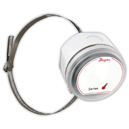
For temperature baseline work, the CBM Surface temperature sensor TE-SNW-E provides non-contact readings that don't disturb your system. Mount these sensors at critical points and record readings across multiple operational states: idle, partial load, and full load. Temperature variations of 5-10°C between baseline and current readings typically signal bearing wear, refrigerant leaks, or electrical connection issues.
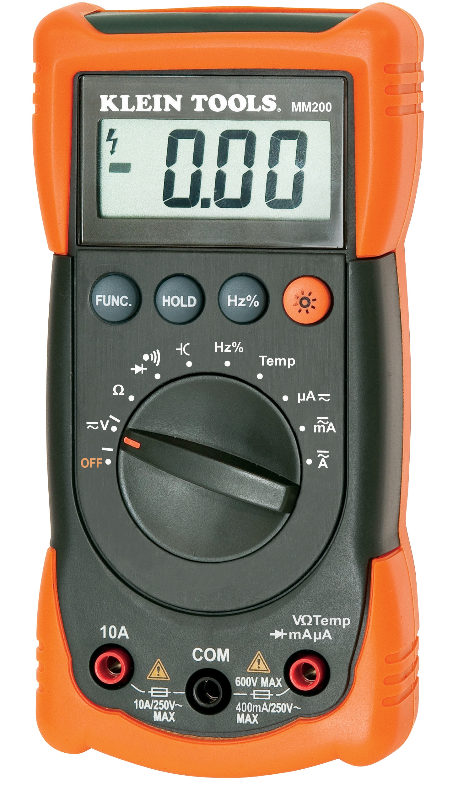
Electrical baselines require more sophisticated tools. The CBM Automatic multimeter MM420 captures voltage, current, and resistance data with auto-ranging capability. For HVAC compressors, electrical motors, and control circuits, record baseline readings when equipment is operating normally, then repeat measurements monthly to track trends.
Documentation Strategy
Maintain a simple spreadsheet with these columns:
- Equipment identifier
- Measurement type (temperature, voltage, pressure, etc.)
- Location
- Baseline value (date recorded)
- Current measurement (date)
- Variance percentage
- Notes
This enables quick pattern recognition. When you see the same parameter drifting consistently, you've identified a developing problem.
Section 2: Diagnosing Pressure System Issues Through Detection
Understanding Your Pressure Readings
Pressure measurement is often the earliest indicator of system problems. A compressor losing capacity, a leaking valve, a clogged filter, or deteriorating seals all show up in pressure data before other symptoms appear.
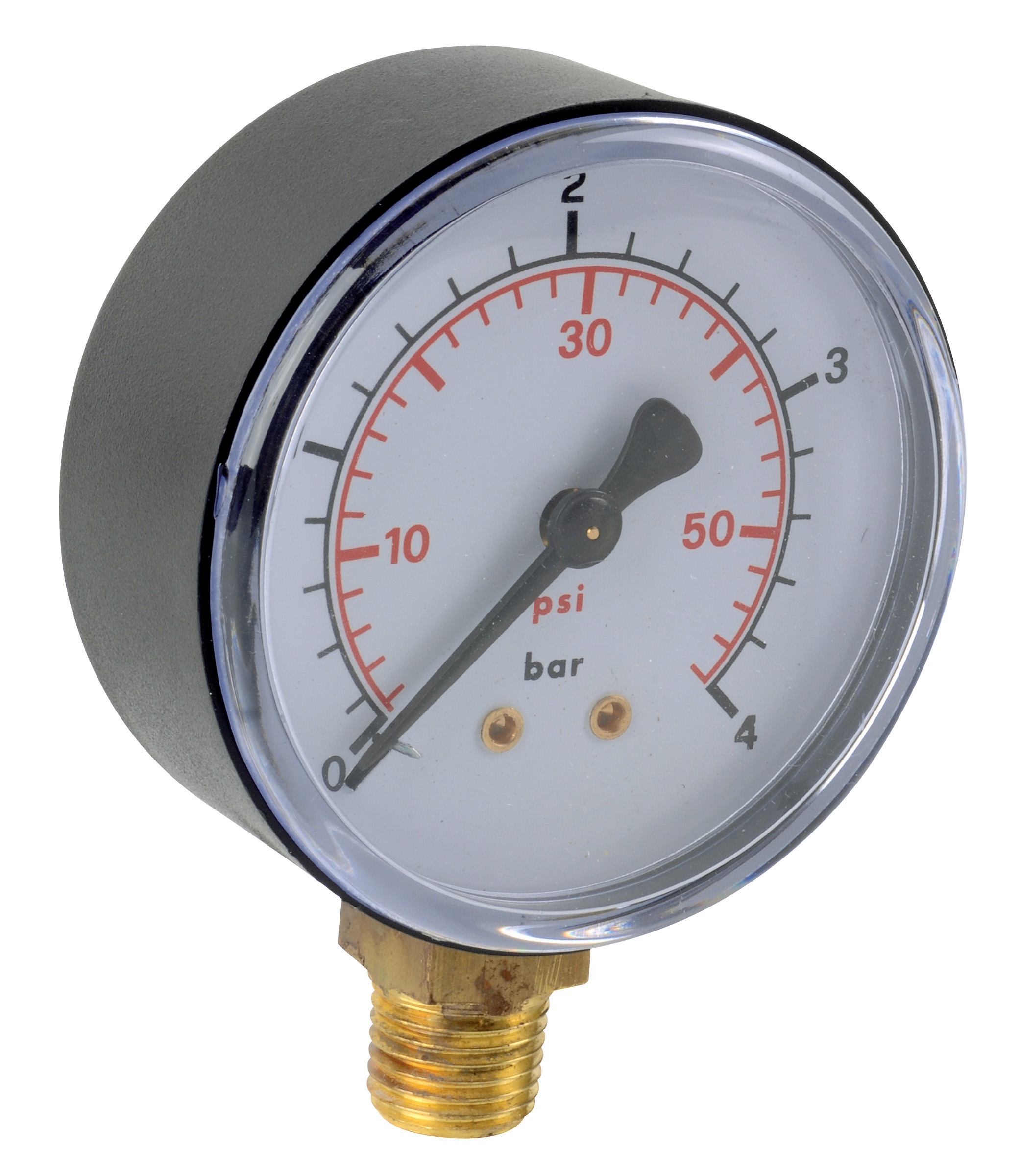
For low-pressure applications like HVAC systems or pneumatic controls, the CBM Green ABS pressure gauge D63 0/+1bar G1/4 provides direct, analog readouts suitable for control panel mounting. These gauges withstand vibration and thermal cycling without requiring electronics or calibration.
For high-pressure hydraulic systems, industrial gas bottles, and compressor discharge lines, the CBM ABS green gauge D50 0/+250bar G1/4 handles demanding environments. These instruments measure pressure directly at the source, providing immediate feedback without electrical dependencies.
Diagnostic Procedures
Scenario 1: Gradual pressure drop over days or weeks
This pattern indicates a slow leak. Procedure:
1. Record current pressure at system startup (cold condition)
2. Record pressure after 30 minutes of operation
3. Record pressure after 2 hours
4. If pressure rises then stabilizes, the problem is external: check hose connections, valve packing, gauge isolation ball valves
5. If pressure continues climbing but fails to reach specification, the problem is internal: suspect compressor valve damage, internal leaks, or regulator drift
6. To isolate the leak, shut down the system and monitor pressure drop over 4 hours with the system static. A 5%+ pressure drop indicates internal leakage
Scenario 2: Pressure fluctuations during normal operation
This suggests load-unload cycle problems or faulty pressure switches:
1. Verify actual system demand—check the load being served
2. Compare current pressure fluctuation range to historical data
3. If range has widened, the pressure regulator needs cleaning or replacement
4. If fluctuations are erratic rather than cyclical, the pressure transducer or switch may have failed
Scenario 3: Pressure spike during startup
Normal startup surge should be 10-15% above running pressure. Spikes exceeding 25%:
1. Check for slug of liquid in the discharge line
2. Verify relief valve setting and condition
3. Examine startup sequence logic—some equipment ramps pressure deliberately
Recording Pressure Trends
Don't just note the current number. Record pressure data at consistent times:
- Startup pressure (equipment cold)
- Operating pressure (steady state)
- Load pressure (peak demand)
- Idle/unloaded pressure
- Shutdown pressure
Over weeks and months, these trends reveal degradation. A compressor losing 2-3 PSI per month until it can no longer maintain specification requires replacement—but you caught it during planning, not during crisis.
Section 3: Gas Detection and Safety-Critical Monitoring
Multi-Point Gas Detection Systems
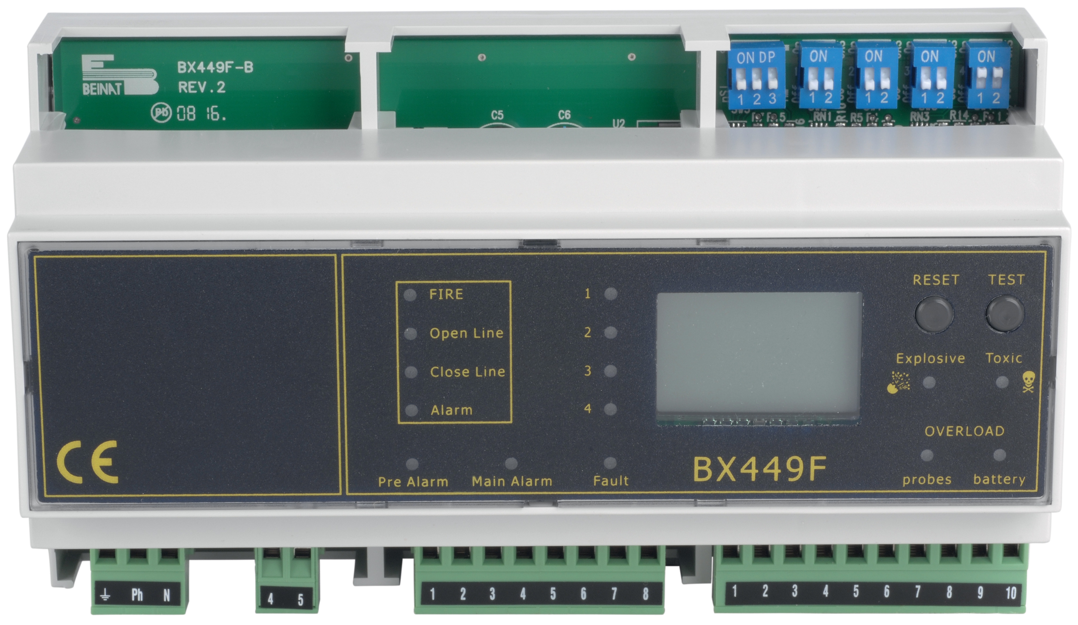
Facilities handling refrigerants, propane, natural gas, or operating in potentially hazardous atmospheres need continuous gas detection. The CBM Gas detection center Din rail 8 probes - 12V provides centralized monitoring for up to eight separate detection points, ideal for multi-zone facilities.
Installation Troubleshooting
Gas detection effectiveness depends on proper probe placement:
For refrigerant leaks (denser than air):
- Place probes in low points: under equipment, in drain sumps, near floor level in mechanical rooms
- Check readings seasonally—warmer ambient temperatures increase evaporation rates and detection sensitivity
- Test system monthly using a known-safe refrigerant or certified test gas
- Mount probes high: near ceiling, in attics, above storage cabinets
- Verify probe response time monthly—sensors degrade and may not detect leaks within acceptable safety windows
Maintenance Team Procedures
1. Weekly visual inspection: Verify all probe indicators are functioning and showing "normal" status
2. Monthly calibration check: Use test gas per manufacturer specifications to confirm sensor response
3. Quarterly download logs: Gas detection systems record events; review any "near-alarm" incidents to investigate root causes
4. Semi-annual professional service: An authorized technician should verify calibration against traceable standards
When you detect a gas alarm:
- Evacuate the area immediately
- Shut down relevant equipment
- Ventilate the space
- Document the incident with date, time, location, and detected gas type
- Investigate the source before resuming operation
Maintenance teams often dismiss gas detection alarms as "sensor drift," but each alarm is a gift—it's your system warning you of a real hazard before it becomes dangerous. Treat every alarm seriously and investigate thoroughly.
Section 4: Integrating Measurement & Detection Data for Predictive Analysis
Building Your Maintenance Dashboard
Measurement & Detection only prevents failures when your team actually uses the data. Create a simple monthly review process:
1. Temperature trending: Flag any equipment running 10°C+ hotter than baseline; order bearing or motor inspection
2. Electrical analysis: Investigate voltage drops exceeding 3% or current draw changes above 20%; these indicate connection degradation or load changes
3. Pressure analysis: Track and project pressure capability; schedule replacement when trending shows maintenance pressure requirements within 10% of maximum service rating
4. Gas detection: Investigate every alarm and false alarm to understand system sensitivity and identify leak sources
Common Detection Failures and Solutions
Temperature sensor not reading
If your surface temperature sensor stops responding:
- Verify power supply at the device
- Check mounting—ensure sensor face is in direct contact with measured surface
- For infrared sensors, verify lens is clean (dust/condensation blocks readings)
- Test with a reference thermometer held next to the sensor
When your MM420 multimeter produces variable results:
- Allow 2-3 minutes warm-up time before reading
- Check battery condition (weak batteries cause drift)
- Verify test leads are fully seated in input jacks
- Test the multimeter itself against a known reference voltage
- High electrical noise may require shielded test leads
Analog gauges like the pressure gauge D63 and D50 gauge can appear to give variable readings due to:
- Vibration (normal in industrial equipment)
- Temperature changes affecting gauge fluid viscosity
- Air trapped in gauge isolation lines—bleed isolation ball valves to remove air
- Gauge tapping—vibration causes needle oscillation, read at the center of oscillation
Compare two identical gauges side-by-side. If readings differ by more than 2%, the gauges need re-calibration.
Gas detection drift
The gas detection system may show spurious readings if:
- Probes are installed near HVAC returns (dilution reduces detection capability)
- Ambient temperature exceeded sensor operating range
- Probes haven't been serviced; sensors need cleaning
- Too many false alarms indicate the system requires recalibration—this is the manufacturer's job, not field adjustment
Building Organizational Knowledge
Your team's experience becomes your competitive advantage. Document what you learn:
- When you find a failed bearing, note the temperature progression that preceded failure
- When you discover electrical connection degradation, record the resistance values and voltage drop patterns
- When you locate a gas leak, document the probe that detected it first and the response time
This data trains your team and creates institutional memory. New technicians learn faster. Your maintenance decisions become evidence-based rather than intuition-based.
Conclusion
Measurement & Detection transforms maintenance from reactive firefighting into strategic asset management. Your team has the tools—the challenge is discipline in data collection and analysis.
3G Electric's 35+ years of equipment distribution worldwide has shown us that the best-maintained facilities aren't those with the newest equipment; they're the ones with the most rigorous measurement protocols. Small investments in proper monitoring tools and procedures pay enormous dividends in reduced downtime, extended equipment life, and improved safety.
Start this week: identify your three most critical systems, establish baseline measurements, and commit to monthly reviews. Within three months, you'll have trends. Within six months, you'll be preventing failures. That's the power of Measurement & Detection done right.