Understanding Industry Applications in HVAC Fluid Systems
Industry applications for HVAC contractors extend far beyond standard heating and cooling installations. Modern commercial and industrial HVAC systems integrate complex fluid delivery mechanisms, high-pressure components, and precision spray technologies that demand sophisticated diagnostic capabilities. With 3G Electric's 35+ years of experience distributing industrial equipment globally, we've helped thousands of contractors master the technical foundations needed to maintain, troubleshoot, and optimize these critical systems.
Fluid system failures in HVAC applications don't always announce themselves dramatically. A 2-3 bar pressure drop might seem minor, but it signals deeper issues: worn seals in your pump assembly, debris in your regulator, or calibration drift in safety systems. HVAC contractors who understand industry applications—how components interact under real-world conditions—can diagnose problems before they cascade into expensive downtime.
Pressure Regulation Diagnostics: From Setpoint to Field Reality
One of the most common industry applications for HVAC contractors involves managing pressure regulation across multi-stage systems. Many contractors treat pressure regulators as "set it and forget it" components, but proper diagnostics require active monitoring and systematic troubleshooting.
Identifying Pressure Instability Issues
When a system shows fluctuating outlet pressure—your gauge reads 37 mbar one moment, 33 mbar the next—the problem rarely lies in the regulator alone. Start with these diagnostic steps:
- Verify inlet pressure stability: High-pressure oscillations upstream (within 20% of setpoint) suggest pump cavitation or loose fittings
- Check for downstream blockages: A partially blocked nozzle or valve creates backpressure that destabilizes regulator response
- Assess vent port condition: The Francel B25/37mb pressure regulator features a 10 mm vent size; any restriction here—dust, debris, or sealant residue—prevents proper relief valve operation
- Inspect regulator diaphragm wear: Over 5,000 operating hours, even quality regulators experience diaphragm fatigue, reducing sensitivity to pressure changes
Industry applications mandate that pressure relief systems operate predictably. For systems using the Francel B25/37mb with integrated safety relief, conduct quarterly relief testing:
1. Record baseline outlet pressure with normal load
2. Gradually increase inlet pressure while monitoring outlet pressure
3. Relief should activate within ±0.5 bar of the setpoint
4. Verify vent discharge flows freely during relief operation
5. Confirm outlet pressure stabilizes when inlet pressure drops
If relief activation occurs erratically—sometimes at 38 mbar, sometimes at 35 mbar—the regulator requires professional recalibration or replacement. This unpredictability creates cascading problems throughout your system.
High-Pressure Pump Diagnostics: Flow, Pressure, and Power Consumption Analysis
Industry applications in HVAC frequently involve high-pressure fluid delivery for cleaning systems, specialized coating applications, or integrated process support. Diagnosing pump performance requires understanding the relationship between three critical parameters: volumetric flow, discharge pressure, and power input.
Flow Rate Troubleshooting
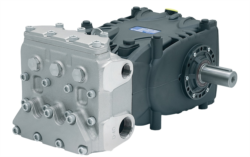
The Pratissoli KF30 pump delivers 106 L/min at 200 bar with 40 kW input—but real-world performance often deviates. When flow drops below specification:
- Check inlet conditions first: Inadequate supply pressure or cavitation at pump inlet reduces displacement; verify inlet pressure exceeds 0.5 bar
- Measure actual displacement: Flow decline of 10-15% typically indicates internal wear; seal degradation or valve leakage reduces volumetric efficiency
- Assess circuit losses: Restrictive filters, excessive hose routing, or partially closed isolation valves consume pressure without contributing to useful work
- Verify drive coupling: Loose or worn couplings cause slip; actual flow may reach only 85-90% of theoretical output
For the Pratissoli MW40 (211 L/min, 210 bar) and larger industrial pumps, pressure stability under varying load conditions reveals system health:
1. Steady-state pressure verification: Run the pump at full displacement with no external load; pressure should remain below 10 bar
2. Load ramp testing: Gradually increase system load in 25 bar increments; pressure rise should be linear and predictable
3. Pressure spikes and oscillation: Sudden pressure jumps (>15 bar in <1 second) indicate relief valve chatter or flow restriction
4. Sustained high pressure: If discharge pressure remains elevated (>220 bar) without proportional flow demand, suspect a stuck relief valve
Power Consumption Analysis
For troubleshooting efficiency and identifying component degradation, calculate actual power consumption:
Power (kW) = (Pressure × Flow) ÷ 600
If your MW40 pump shows 45 kW consumption while delivering only 190 L/min at 200 bar (theoretical: 211 × 210 ÷ 600 ≈ 74 kW), this indicates:
- Partial cavitation or air entrainment reducing volumetric efficiency
- Internal valve leakage bypassing flow at high pressure
- Coupling slip or drivetrain friction losses
Measure actual power draw monthly; efficiency decline exceeding 5% signals impending failure and justifies preventive replacement before catastrophic breakdown occurs.
Precision Spray System Performance: Nozzle Diagnostics and Pattern Analysis
Modern HVAC industry applications increasingly incorporate precision spray systems for targeted cooling, humidification, or process support. The Euspray flat jet nozzle (1/4" BSPT, 25° angle, index 30) exemplifies these high-performance components, but their effectiveness depends entirely on proper diagnostics and maintenance.
Spray Pattern Degradation Recognition
A functioning nozzle produces a uniform flat jet with consistent spray angle and penetration. When patterns degrade, identify root causes systematically:
- Uneven spray distribution: Indicates internal orifice erosion or partial blockage; the nozzle requires replacement (nozzles aren't field-repairable)
- Spray angle widening: Suggests pressure drop downstream of the nozzle; check all connections, filters, and supply lines for restrictions
- Excessive spray penetration: Occurs when pressure exceeds design specification; verify pump discharge pressure and relief valve setpoint
- Spray angle narrowing: May indicate downstream pressure increase (backpressure from restricted drainage) that compresses the jet
Each nozzle design operates across a specific pressure range. For the index 30 flat jet, typical specifications are:
- Minimum operating pressure: 5 bar (ensures coherent spray pattern)
- Rated pressure: 20-30 bar (design sweet spot for performance)
- Maximum safe pressure: 50 bar (beyond this, orifice erosion accelerates)
Verify nozzle performance by measuring flow at your system's operating pressure and comparing to manufacturer data. If your system runs at 35 bar but flow measures 10% below specification, the nozzle has likely experienced erosion and requires replacement.
Blockage Diagnosis and Prevention
Partial blockages are the most frequent failure mode in precision nozzles:
1. Gradual flow decline: Monitor flow weekly; a 5% drop indicates incipient blockage
2. Spray pattern distortion: The jet becomes asymmetrical before complete blockage occurs
3. Pressure rise without flow increase: System pressure increases while downstream flow stagnates
Prevention involves:
- Installing 100-150 micron filters upstream of nozzles
- Using only clean fluid meeting ISO 4406 16/14/11 cleanliness standards
- Flushing nozzles weekly with low-pressure fluid to clear surface deposits
Compact Pump Systems: Diagnostics for Space-Constrained Applications
Industry applications in retrofit HVAC installations often demand compact, lightweight components that deliver surprising performance in confined spaces. The Interpump E1D1808 (8 L/min, 180 bar, 2.72 kW, 5 kg) exemplifies this category.
Identifying Cavitation and Aeration Issues
Compact pumps are particularly susceptible to cavitation when inlet supply is inadequate:
- Listen for cavitation noise: A crackling or grinding sound during operation indicates vapor bubbles in the pump cavity
- Monitor pressure ripple: High-frequency pressure oscillations (>5 bar amplitude) suggest cavitation; reduce system load or improve inlet supply pressure
- Check for fluid degradation: Cavitation generates heat; discolored or foamy fluid indicates prolonged cavitation damage
- Verify pump orientation: Compact gear pumps require specific inlet position; horizontal or inverted mounting without proper supply head causes immediate cavitation
At 2.72 kW input, the E1D1808 generates continuous heat. Monitor casing temperature:
- Normal operation: 40-50°C above ambient
- Elevated temperature (55-65°C): Check fluid viscosity; cold-start operation or inadequate cooling reduces efficiency
- Excessive temperature (>70°C): Indicates sustained cavitation, high backpressure, or mechanical friction; shutdown and diagnose before damage occurs
For continuous 8 L/min operation, adequate heat dissipation is critical. Portable systems should include small reservoir (minimum 20 L) for thermal mass; integrated circuit designs require periodic idle cycles for cooling.
Practical Maintenance Intervals and Performance Trending
Effective diagnostics require systematic data collection. Establish a maintenance log tracking:
- Weekly: Discharge pressure under load, nozzle flow rate, fluid temperature, visual inspection for leaks
- Monthly: Volumetric efficiency calculation, relief valve setpoint verification, power consumption measurement
- Quarterly: Component noise signature recording, pressure ripple analysis, fluid cleanliness sampling
- Annually: Complete system pressure mapping, efficiency baseline comparison, preventive component replacement assessment
Trending this data reveals emerging problems 2-4 weeks before catastrophic failure. A pump showing 2% monthly efficiency decline may operate for weeks before failing; catching this trend allows scheduled replacement during maintenance windows rather than emergency repairs during peak season.
With 3G Electric's 35+ years distributing fluid system components globally, we've supported HVAC contractors through thousands of diagnostic scenarios. The products we supply—from the Francel pressure regulators ensuring system safety to the Pratissoli MW40 pumps delivering industrial-grade reliability—perform reliably only when contractors understand the industry applications that define real-world performance expectations.
Mastering these diagnostic techniques transforms reactive maintenance into proactive optimization, reducing downtime while extending component life.