Understanding Power Transmission System Failures in Industry Applications
Industrial power transmission systems—comprising high-performance pumps, pressure regulators, spray nozzles, and interconnected piping—represent significant capital investments for Singapore's manufacturing, food processing, chemical, and marine industries. When these systems fail, production halts, service costs escalate, and equipment lifespan diminishes rapidly.
With 35+ years of experience as a global industrial equipment distributor, 3G Electric has supported maintenance teams across Southeast Asia in diagnosing and resolving power transmission failures. The most frequent issues trace to five root causes: cavitation events within pump chambers, pressure regulation drift, component incompatibility during system expansions, flow restriction in delivery lines, and seal degradation from thermal stress.
This guide provides maintenance teams with systematic troubleshooting procedures to isolate faults, verify component performance, and restore system reliability without unnecessary part replacement or extended downtime.
Section 1: Diagnosing Pump Cavitation and Flow Delivery Problems
Cavitation occurs when pressure at the pump inlet drops below the vapor pressure of the working fluid, creating vapor bubbles that collapse violently within the pump chamber. This phenomenon damages impeller surfaces, reduces flow output, generates audible noise (resembling gravel flowing through pipes), and dramatically shortens pump life.
Identifying Cavitation Symptoms:
- Audible Indicators: Listen for characteristic chattering or grinding sounds during pump operation, particularly during acceleration or high-load cycles. Record sound frequency and intensity using smartphone audio recording for baseline comparison across maintenance intervals.
- Performance Degradation: Compare current flow rates against baseline specifications. A 10-15% reduction in flow delivery at consistent motor speed often signals early-stage cavitation. Measure actual outlet pressure using calibrated gauges and compare to pump nameplate ratings.
- Vibration Analysis: Excessive vibration at pump mounting feet increases from normal baseline. Use a digital vibration meter (0-200 Hz range) and document measurements; cavitation typically elevates vibration in the 50-100 Hz band.
- Visual Inspection: Examine the pump exterior for leakage at shaft seals. Cavitation generates micro-vibrations that accelerate seal wear, causing weeping that progresses to steady drips.
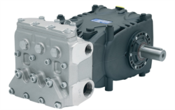
1. Record inlet pressure using a low-pressure gauge installed at the pump suction port (typical industrial pumps like the Pratissoli KF30 require minimum inlet pressure of 0.5 bar for reliable operation).
2. Verify inlet line diameter matches pump specifications; undersized suction lines (e.g., 1/2" hose on a pump rated for 3/4" inlet) create excessive velocity and pressure drop.
3. Inspect inlet strainer condition—accumulated particulates reduce suction flow. Replace if pressure differential across strainer exceeds 0.3 bar.
4. Check fluid reservoir level; low levels expose suction lines to air intake, introducing aeration that manifests as foaming in the discharge line.
5. Measure discharge pressure simultaneously with inlet pressure. The pressure differential should match pump specifications; excessive differential (>20% above rated) confirms cavitation risk.
6. If cavitation persists after addressing inlet conditions, the pump impeller may require replacement. High-performance industrial pumps like the Pratissoli MW40 (211 L/min capacity) suffer accelerated wear; document run hours and maintenance history to justify replacement timing to operations management.
Prevention and Maintenance:
Inspect inlet strainers monthly in high-utilization operations (>40 hours/week). Maintain fluid reservoir cleanliness per ISO 4406 16/14/11 standards through scheduled filtration. Schedule suction line inspection annually, particularly for systems operating near cavitation thresholds (pump inlet pressure <1.0 bar absolute).
Section 2: Pressure Regulation System Drift and Inconsistency
Pressure regulators like the Francel B25/37mb with integrated safety relief maintain outlet pressure within specified ranges despite inlet pressure fluctuations. When regulators drift—gradually allowing outlet pressure to rise or fall outside tolerance—downstream equipment performance degrades, spray patterns become inconsistent, and seal leakage accelerates.
Common Pressure Regulation Failures:
- Creep Drift: Outlet pressure slowly rises over hours or days despite stable inlet conditions. Typical cause is internal spool or poppet valve stiction (sticky valve movement) from contaminated fluid or thermal stress.
- Hunting Oscillation: Outlet pressure cycles repeatedly (±2-5 bar swings) rather than stabilizing. This occurs when regulator gain (responsiveness to pressure changes) is set too aggressively, creating feedback oscillation.
- Dead-Band Insensitivity: Regulator fails to maintain outlet pressure—pressure varies ±10 bar or greater from setpoint despite normal inlet supply. This indicates worn poppet seals or spool spools that no longer form tight closure.
1. Install pressure gauges immediately upstream and downstream of the regulator. For the Francel B25/37mb unit, downstream gauge should stabilize at 37 mbar (±2 mbar).
2. Record inlet pressure stability; if inlet pressure fluctuates >±5% from mean, address upstream pressure source first (verify pump discharge pressure consistency) before blaming the regulator.
3. Log outlet pressure readings every 5 minutes for a 30-minute period with system under steady load. Plot data on graph paper: linear drift indicates creep; oscillating pattern indicates hunting.
4. Cycle the system between full flow and blocked-discharge conditions three times, recording outlet pressure during each transition. Response time should be <2 seconds; slower response suggests internal spool wear.
5. If outlet pressure drifts >10% from setpoint, drain the regulator and inspect the internal poppet valve for particulate embedding or surface scratching. Small particles (10-20 microns) prevent tight sealing and cause creep drift.
6. Compare outlet pressure with and without load (full flow vs. zero flow at blocked discharge). Regulator compensation design should maintain ±2 mbar consistency; larger variance indicates wear or thermal sensitivity requiring calibration adjustment.
Maintenance and Calibration:
Regulators require scheduled maintenance every 12 months or after 2000 operating hours. Contaminated fluid is the primary failure mode; implement system-wide filtration to ISO 4406 16/14/11 or better. If regulator drift exceeds tolerance after cleaning, schedule professional recalibration or replacement. Document all regulator adjustments with date, technician initials, and before/after pressure readings for traceability.
Section 3: Spray Nozzle Performance Degradation and Pattern Loss
Industrial spray nozzles like the Euspray flat jet nozzle HP 1/4" M BSPT with 25° spray angle deliver targeted spray patterns for cleaning, coating, and cooling applications. Nozzle performance deteriorates through three mechanisms: internal erosion from high-pressure flow, orifice blockage from particulates or crystallization, and external wear of the spray angle surfaces.
Identifying Nozzle Degradation:
- Spray Pattern Distortion: The 25° spray angle becomes irregular or split. Compare current spray geometry against a photograph of proper operation using consistent lighting and camera angle.
- Reduced Flow Volume: Flow measurement decreases while inlet pressure remains constant. A 15-20% reduction typically indicates internal erosion; >20% suggests partial orifice blockage.
- Pressure Rise at Constant Flow: Maintaining the same outlet flow requires elevated inlet pressure. This compensatory behavior confirms internal restriction building progressively.
- Dry Zones or Dead Spots: The spray pattern develops areas lacking liquid coverage, indicating orifice asymmetry from erosion or blockage.
1. Measure inlet pressure to the nozzle and collect outlet flow over a timed interval (30-60 seconds) into a calibrated container. Calculate actual flow rate (L/min) and compare against nozzle specification (typically 15-25 L/min for flat jet nozzles at 200 bar).
2. Document spray pattern geometry using a cardboard target held at standard distance (typically 300 mm). Mark the wet area with pencil; photograph the target with consistent lighting. Repeat measurement weekly to track pattern evolution.
3. Isolate the nozzle from the system and inspect the visible orifice opening using a magnifying glass (10x magnification minimum). Look for mineral deposits, crystallization, or particle embedding. For high-calcium water applications (common in Singapore), mineral buildup occurs within 200-300 operating hours.
4. If blockage is suspected, attempt backflushing by reversing fluid flow through the nozzle at inlet pressure 50% above normal operation. Use a compatible fluid (typically mineral oil or biodegradable ester for industrial nozzles) to avoid damaging seals.
5. If backflushing restores flow and pattern geometry, the blockage was temporary. Implement weekly backflush cycles in the maintenance schedule for water-based applications.
6. If blockage persists or spray pattern remains distorted after backflushing, the nozzle requires replacement. High-wear applications (>40 hours/week continuous operation) justify replacement at 12-month intervals regardless of apparent condition to prevent unplanned production stoppages.
Optimal Nozzle Maintenance:
Install a 100-micron strainer immediately upstream of spray nozzles in systems using water or glycol-based fluids. Maintain strainer cleanliness by monitoring pressure differential; replace when differential exceeds 0.5 bar. For systems operating with mineral oil, 150-micron strainers are adequate. Document all nozzle replacements with date, operating hours, flow measurements, and visual condition notes to establish life expectancy baselines for your specific application.
Section 4: Component Integration and System Compatibility Issues
When maintenance teams integrate additional equipment into existing power transmission systems—adding secondary pumps, expanding pressure capacity, or retrofitting nozzle arrays—compatibility conflicts between components degrade overall system performance. The most common integration failures involve pressure mismatch, flow incompatibility, and seal material degradation from fluid chemistry changes.
Identifying Integration Failures:
- Unexpected Pressure Spikes: Outlet pressure rises 20-30% above normal after adding new components, suggesting inadequate relief valve sizing or regulator response limitation.
- Cavitation in Secondary Pumps: New pump stages cavitate immediately upon commissioning, indicating inadequate inlet pressure supply from primary pump.
- Flow Starvation: System operates at partial flow despite full motor input, suggesting series-connected pumps with insufficient pressure overlap or parallel pumps with unequal pressure drops across suction lines.
- Thermal Runaway: System fluid temperature rises rapidly after component integration, indicating hydraulic losses from mismatched flow characteristics or excessive throttling across relief valves.
1. Pre-Integration Baseline: Before adding components, document the existing system's performance: measure pump discharge pressure and flow under no-load and full-load conditions; record system fluid temperature after 30 minutes steady operation; verify all regulator and relief valve setpoints using calibrated gauges.
2. Component Specification Verification: Confirm that new components (pumps, regulators, nozzles) match system specifications:
- For primary pump systems, the secondary pump inlet pressure should equal or exceed 0.5 bar. If integrating the Interpump E1D1808 gear pump (8 L/min at 180 bar) as a secondary stage, verify that primary pump discharge pressure exceeds 2.0 bar at the secondary pump inlet.
- Verify pressure relief valve sizing accommodates combined flow of all pump stages. A system combining KF30 pump (106 L/min) with E1D1808 pump (8 L/min) requires relief valve capacity of ≥114 L/min.
- Confirm that all components operate within compatible pressure ranges; mixing pumps rated 200 bar with components rated 280 bar creates unnecessary thermal stress and accelerated seal wear.
3. Post-Integration Testing: After component integration, measure:
- Outlet pressure under no-load (blocked discharge) and full-load conditions
- Flow rates for each pump stage independently and combined
- System fluid temperature after 60 minutes steady operation
- Pressure differential across relief valves (should be 10-15 bar above system operating pressure)
- Inlet pressure to all secondary stages (should exceed minimum specification)
4. Compatibility Conflict Resolution: If measurements deviate from expected values:
- If outlet pressure spikes >20% above intended setpoint, verify relief valve is correctly sized and setpoint adjusted. Undersized relief valves throttle excessively, generating heat and wasting energy.
- If secondary pump cavitates, increase primary pump outlet pressure by adjusting relief valve setpoint upward (typically 5-10 bar increments). Verify increased pressure does not exceed component ratings.
- If thermal runaway occurs, identify the source by measuring pressure differential across each component. Excessive differential indicates flow mismatch; throttle high-flow stages using proportional flow control valves.
5. Seal Material Compatibility: When integrating components from different manufacturers (Pratissoli pumps with Euspray nozzles, for example), verify seal materials are compatible with the system fluid:
- Mineral oil systems typically use nitrile (NBR) seals; these swell excessively in biodegradable ester fluids.
- Biodegradable systems require PTFE or fluorocarbon (FKM) seals to prevent leakage and seal failure.
- Document the fluid type and seal material for each integrated component; mixing incompatible seals leads to leakage within weeks of commissioning.
Integration Success Criteria:
After component integration, the system should demonstrate:
- Outlet pressure within ±2% of design setpoint under all load conditions
- Fluid temperature <5°C above baseline after steady-state operation
- Inlet pressure to all secondary stages within specified minimums
- No audible cavitation, grinding, or unusual vibration
- All pressure gauges reading smoothly without oscillation or creep drift
Document post-integration performance baselines for comparison during future maintenance cycles. These baselines enable early detection of degradation trends (cavitation onset, regulator drift, or seal wear) before they become operational failures.
Preventive Maintenance Schedule for Power Transmission Systems
Maintenance teams should implement interval-based inspections aligned with equipment utilization:
- Monthly: Visual inspection for leaks, audible assessment for cavitation or grinding, strainer pressure differential verification, fluid level check
- Quarterly: Pressure gauge calibration verification, pump flow measurement, spray nozzle pattern documentation, thermal imaging of pump housing and motor
- Semi-Annual: Seal and coupling inspection, regulator performance verification under load, relief valve setpoint validation, component contamination analysis
- Annual: Fluid sampling and ISO cleanliness analysis, pump efficiency testing, regulator internal inspection and cleaning, system integration compatibility audit
Document all measurements, observations, and corrective actions in a maintenance log. Trend analysis of pressure, temperature, and flow measurements across 12-month periods enables predictive maintenance—identifying equipment likely to fail within 1-3 months so replacement can be scheduled during planned shutdowns rather than emergencies.