Fuel Flame Detection Failures in Oil & Gas Burner Controls: Troubleshooting Guide for Global Industrial Operations
Fuel flame detection failures represent one of the most challenging diagnostic scenarios in industrial burner control systems globally. Unlike pilot light ignition failures or lockout conditions that produce clear external symptoms, flame detection system failures often manifest as intermittent shutdowns, nuisance lockouts, or delayed flame recognition—symptoms that can mask the root cause across multiple subsystems. Maintenance teams and service engineers frequently encounter situations where a burner shuts down despite visible flame, or where the control system fails to respond to legitimate flame presence. These scenarios demand systematic diagnostic methodology that isolates failure points at the sensor, optical path, and control electronics levels. This guide provides technical procedures, equipment specifications, and field-proven diagnostic approaches for troubleshooting flame detection failures across infrared sensors, photo-resistive cells, and integrated control systems.
Understanding Fuel Flame Detection System Architecture
Modern fuel burner control systems employ three primary flame detection technologies, each with distinct failure modes and diagnostic requirements. Infrared (IR) flame detectors operate by sensing radiation in the 800–1100 nanometer spectral range, making them sensitive to the characteristic emission profile of burning fuel. Photo-resistive cells measure visible light intensity through variable resistance changes, while phototransistor-based sensors provide semiconductor-level detection with faster response times. The fundamental architecture of any flame detection system includes the sensing element itself, an optical path from the flame to the sensor, and a control relay that interprets the sensor signal and initiates safety actions when flame presence cannot be verified.
The critical distinction between flame detection failures and other burner control faults lies in the intermediate processing stage. A failed thermocouple in a pilot light system produces no signal—the circuit is broken. A failed flame detector, by contrast, may produce electrical signals, but those signals may be corrupted by environmental interference, optical fouling, sensor aging, or signal processing errors in the relay module. This complexity means that troubleshooting flame detection failures requires measurement at multiple points in the signal chain, not merely verification of component continuity.
In global industrial applications, environmental factors significantly influence flame detection reliability. Tropical climates with high humidity and salt-laden air accelerate optical window fouling and sensor degradation. Industrial environments with significant infrared background radiation—from adjacent furnaces, steam pipes, or solar ingress through windows—create false positive signals that challenge sensor discrimination. Understanding these environmental parameters is essential for differentiating between inherent sensor failure and application-specific interference patterns.
Technical Specifications and Diagnostic Points for Flame Detection Components
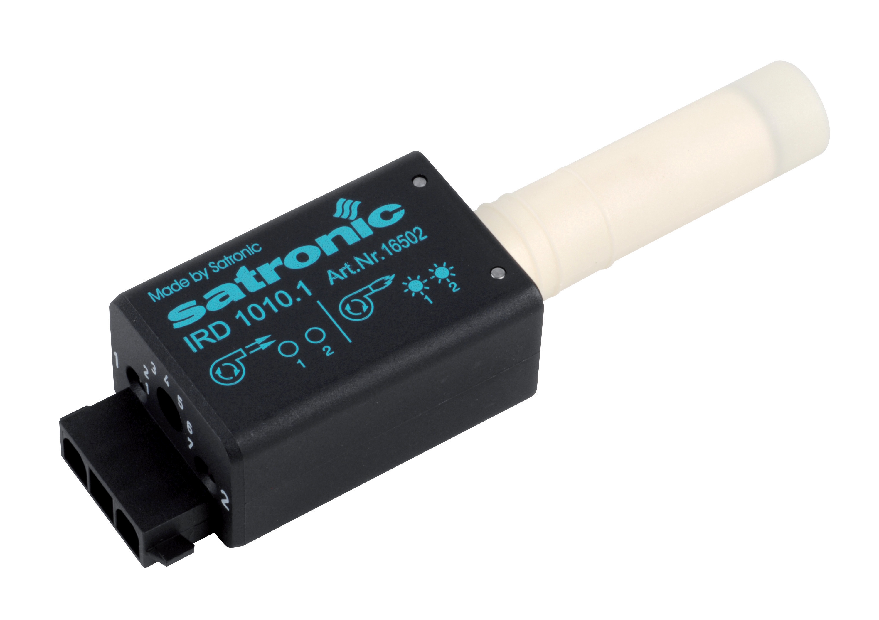
The IRD 1010 blue cell infrared flame detector represents a widely deployed fuel flame monitoring solution designed specifically for oil burner applications. With a spectral sensitivity range of 800–1100 nanometers (maximum response at 950 nm with daylight filter), this sensor provides selective detection of fuel flame radiation while rejecting solar and incandescent interference. The technical specifications establish key diagnostic reference points: the unit operates at 220/240 V (±15% to +10% tolerance), responds to flame flicker frequencies between 15–250 Hz at −12 dB, and requires any mounting position with IP 41 environmental protection rating.
When diagnosing infrared detector failures, the first measurement point is supply voltage at the detector terminals. Voltage outside the ±15%/+10% envelope will suppress sensor response even if the optical path is clear and flame is present. Field experience shows that fluctuating supply voltages—common in facilities with heavy motor loads or aging electrical infrastructure—cause intermittent flame detection failures that correlate with production cycle timing rather than true equipment degradation.
Photo-resistive cell-based systems, such as the Cell 8207, operate on a fundamentally different principle: variable light intensity produces proportional resistance changes that are amplified by relay electronics. The Cell 8207 operates effectively up to 100°C, establishing a maximum thermal boundary for safe operation. Failures in photo-resistive systems often manifest as signal drift—gradual loss of sensitivity—rather than complete signal loss. This drift results from phosphor layer degradation on the photoresistive element itself, a time-dependent failure mode that correlates with cumulative light exposure and thermal cycling history.
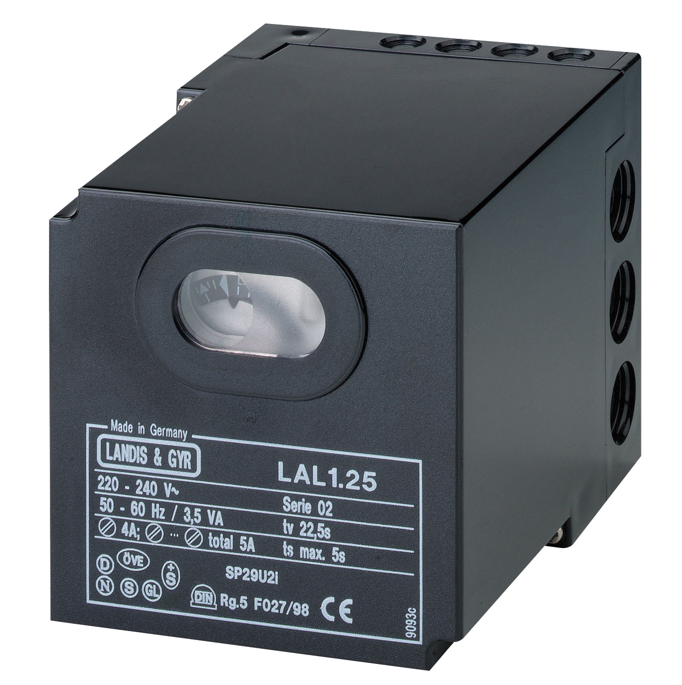
The LAL 2.14 safety relay provides the interface between flame detection sensors and burner shutdown logic. This intermittent-duty control system incorporates flame monitoring options for QRB1, QRC1, or RAR-type sensors, establishing compatibility across multiple sensor architectures. When a flame detection failure is suspected, the LAL 2.14 relay provides accessible test points for signal verification: the flame signal input terminal should display measurable voltage change when flame is present versus absent. Absence of signal voltage change at this terminal—despite visible flame at the burner—narrows the failure to either sensor output or optical path obstruction.
Systematic Diagnostic Procedure for Flame Detection Failures
Step 1: Visual Inspection and Environmental Assessment
Before measuring electrical signals, conduct a physical inspection of the optical path. Examine the sensor window, protective sight glass, and any intervening optical elements for fouling, corrosion, moisture, or mechanical debris. In global industrial environments, this inspection often reveals salt spray corrosion on sensor housings (coastal facilities), mineral scale buildup from steam condensation (steam boiler applications), or oil mist accumulation (in mechanical spaces with inadequate ventilation). Document the condition photographically if the facility has documented failure trends.
Step 2: Supply Voltage Verification
Measure DC or AC supply voltage at the sensor power terminals using a calibrated multimeter. For the IRD 1010 detector, acceptable range is 187–264 V AC (220/240 V ±15%/+10%). Record the voltage reading; values below 200 V or above 260 V should prompt investigation of facility electrical infrastructure before condemning the sensor.
Step 3: Optical Window Cleaning Protocol
If visual inspection reveals fouling, clean the optical window using lens-grade isopropyl alcohol (>90% purity) and lint-free microfiber cloth. Allow 5–10 minutes for complete solvent evaporation before returning the burner to service. Many reported flame detection failures resolve at this step, indicating that optical contamination rather than sensor failure was the root cause.
Step 4: Sensor Signal Output Measurement
With the burner operating and flame established, measure the sensor output signal at the control relay input terminal. For photo-resistive cells, the output should show measurable resistance change (typically 5–50 kΩ variation depending on cell type and relay design). For infrared detectors, output voltage typically ranges from 1–5 V depending on flame intensity and distance. If no signal change occurs when flame is present, the sensor element itself requires replacement.
Step 5: Relay Response Verification
With the sensor signal confirmed present, verify that the safety relay responds appropriately. Block the sensor view of the flame (using a ceramic card or aluminum foil temporary obstruction) and confirm that the control relay initiates shutdown sequence within 5 seconds. If the relay fails to respond to signal loss, the relay module—not the sensor—is the failed component.
Real-World Application Examples and Failure Pattern Analysis
Case Study 1: Coastal Petrochemical Facility (Middle East Gulf Region)
A major oil refinery's auxiliary boiler burner was experiencing nuisance shutdowns every 8–12 hours during normal operation. The IRD 1010 blue cell detector had been installed 18 months prior. Field inspection revealed orange-white salt spray corrosion on the sensor housing exterior, with white crystalline deposits visible inside the optical window protective cover. Window cleaning resolved the immediate failure; however, the facility subsequently installed a protective stainless steel sight tube with purge air capability (continuous low-pressure compressed air flow across the optical window) to prevent recurrence. This application modification transformed the failure pattern from recurring shutdowns to zero lockouts over 24 months of operation.
Case Study 2: Industrial Steam Boiler (Southeast Asia Manufacturing Facility)
A textile manufacturing facility's steam boiler burner exhibited erratic flame recognition requiring manual restart 3–5 times per shift. The facility used a Cell 8207 photo-resistive detector installed 4 years prior. Diagnostic measurements showed sensor output signal present but at only 40% of expected amplitude (compared to identical backup burner on same steam line). Thermal imaging revealed the sensor mount temperature at 115°C, exceeding the Cell 8207's 100°C maximum operating temperature specification due to radiant heat from the boiler casing. Relocation of the sensor mount 30 cm further from the boiler and installation of a ceramic heat shield normalized sensor temperature to 85°C. Signal amplitude recovered to 95% of baseline, eliminating the restart failures.
Case Study 3: Multi-Burner Hot Air Generator (European Manufacturing)
A facility operating three parallel hot air generators (each with independent burner controls) experienced intermittent failures on Generator #2 only. Investigation revealed that Generators #1 and #3 had recently been refurbished with new infrared detectors, while Generator #2 retained its original detector—now 7 years old. Comparative voltage measurements showed that the aged detector required flame twice as close (50% proximity) to generate equivalent signal to new units. The root cause was not detector failure but normal sensor sensitivity degradation. Replacement with a new detector restored normal operating distance and eliminated proximity-related failures. This case demonstrates that flame detection failures often result from cumulative aging rather than catastrophic component failure, requiring periodic preventive sensor replacement rather than failure-response replacement.
Selection Criteria and Preventive Maintenance Best Practices
Environmental Compatibility Assessment
When selecting flame detection components for new installations or replacements, evaluate the operating environment against sensor specifications. Coastal or high-moisture environments demand infrared detectors with superior corrosion resistance and protective sight glasses rated for salt spray exposure (ASTM B117 minimum 500-hour rating). High-temperature applications (>100°C ambient sensor location) require infrared detectors or phototransistor sensors rather than photo-resistive cells, which degrade rapidly above their thermal limits.
Preventive Maintenance Program Development
Establish optical window inspection intervals based on environmental severity: monthly in coastal/high-dust environments, quarterly in standard industrial applications, semi-annually in clean environments. Schedule sensor sensitivity checks annually using comparative measurement against known reference conditions or backup detector circuits. For critical applications, implement sensor redundancy using multiple detectors with voting logic—a practice standard in aviation and nuclear applications that is increasingly adopted in industrial burner safety systems.
Component Selection for Global Deployment
The CM391.2 30.5 1.2 relay and CM391.2 10.10 relay represent modern automatic gas burner controls engineered for the EUROBOX series, offering non-volatile lock-out safety functions and compatibility with multiple sensor types. When specifying controls for global deployment, verify that selected relay modules support the full range of sensor types available in your service region—this prevents supply-chain constraints during emergency component replacements.
Conclusion and Next Steps for Industrial Teams
Flame detection system failures demand diagnostic discipline that moves systematically from optical path inspection through electrical signal verification to relay response confirmation. By applying these technical procedures and understanding the environmental and aging factors that drive failure patterns, maintenance teams can distinguish between true sensor failures requiring replacement and application-specific interference that demands design modification or environmental control measures. Global industrial operations benefit significantly from understanding regional environmental factors—salt spray in coastal regions, thermal cycling in temperature-extreme climates, and moisture contamination in high-humidity environments—that influence sensor reliability in ways that laboratory specifications alone cannot predict.
The technical foundation provided by components like the IRD 1010 blue cell detector, Cell 8207 photo-resistive system, and LAL 2.14 safety relay enables thorough diagnostics when proper measurement procedures are applied. For facilities experiencing recurring flame detection failures, we recommend documenting failure timing, environmental conditions at failure moments, and any facility changes (electrical upgrades, adjacent equipment modifications, seasonal climate transitions) that may correlate with symptom onset.
3G Electric's Controls & Safety team maintains extensive field experience with flame detection system installation, troubleshooting, and optimization across global industrial applications. Our technical specialists can provide diagnostic support, component selection assistance for environmental challenges, and preventive maintenance program design tailored to your facility's specific operational profile. Contact our Controls & Safety specialists to discuss your facility's flame detection challenges, request diagnostic support, or explore redundant sensor architecture solutions for mission-critical burner systems.