Pilot Light Ignition Failures: A Troubleshooting Guide for Burner Controls in Singapore
Pilot light ignition failures represent one of the most common operational disruptions in industrial burner systems across Singapore's manufacturing and processing facilities. When a pilot light fails to ignite or extinguishes unexpectedly, the entire burner control sequence becomes compromised, resulting in production downtime and safety concerns. This troubleshooting guide provides industrial professionals with systematic diagnostic procedures to identify root causes and implement corrective measures. Understanding the interaction between pilot burners, thermocouples, ignition electrodes, and control relays is essential for maintaining reliable burner operation and ensuring compliance with safety standards.
Understanding Pilot Light System Architecture and Common Failure Modes
Pilot light systems in modern industrial burners operate as integrated safety and control mechanisms. The pilot flame serves dual purposes: it provides the ignition source for main burner operation and generates a signal (typically through thermocouple voltage) that confirms flame presence to the control system. When this system fails, the malfunction typically occurs at one of three critical points: the ignition electrode, the pilot burner assembly, or the thermocouple sensing circuit.
Ignition electrode failures account for approximately 35-40% of pilot light ignition problems. These electrodes operate under extreme thermal and electrical stress, cycling between room temperature and combustion temperatures repeatedly. The aluminium oxide insulation material used in high-quality pilot burner electrodes (such as those specified in SIT pilot-burner designs) resists impact and abrupt thermal change, but degradation still occurs over extended operating periods. Electrode gap erosion—typically occurring between 0.5mm and 1.5mm spacing—represents the most frequent failure mode, preventing adequate spark generation.
Pilot burner assembly failures constitute the second major category. These failures manifest as inadequate gas flow to the pilot burner head, poor air-gas mixture ratios, or clogging of the burner orifice. Industrial environments in Singapore, particularly facilities with high ambient dust or vibration exposure, experience accelerated burner fouling. The turn-down test specifications for pilot burners—which verify stable flame operation across the full flow range—help identify mixture quality issues during diagnostics.
Thermocouple malfunction represents the third critical failure point. The thermocouple must generate sufficient millivoltage (typically 15-25mV at operating temperature) to hold the safety solenoid valve open. Thermocouple degradation, thermal lag, and electrical continuity loss all prevent proper flame signal transmission to the control relay system. For optimal performance, manufacturers such as SIT specifically recommend using matched thermocouple components—for example, Q334A pilot burners designed for use with Q309A and Q335C thermocouples—rather than universal replacement parts.
Technical Diagnostic Procedures and Component Testing
Effective diagnosis requires systematic testing of each system component using appropriate instrumentation. Begin by visual inspection of the ignition electrode, examining the ceramic insulation for cracks, discoloration, or carbon deposits. Electrode gap measurement using a feeler gauge provides quantitative data; gaps exceeding 3.0mm typically indicate electrode replacement necessity. For SIT pilot-burner assemblies, the characteristic silent operation and corrosion resistance mean that visual degradation—rather than audible changes—signals imminent failure.
Next, verify gas supply pressure to the pilot burner. Pressure measurements should be taken at the pilot gas inlet using a calibrated manometer or digital pressure gauge. Most pilot burners require 100-200 mbar inlet pressure; deviation beyond manufacturer specifications indicates supply-side issues (regulator failure, solenoid valve malfunction, or supply line restriction). The gas control valves in your system, such as the CBM VAS 125R/NW fast gas solenoid valve, contain integrated flow adjustment mechanisms—verify that these adjustment screws have not been inadvertently altered.
Thermocouple testing requires a digital multimeter set to DC millivoltage mode. With the pilot light burning steadily, the thermocouple tip should be fully immersed in the hottest part of the flame (typically the inner blue zone). Record the millivoltage reading; values below 12mV indicate thermocouple failure or improper positioning. Perform continuity testing across the thermocouple connections; any resistance reading above 5 ohms suggests electrical degradation. Temperature measurement using an infrared pyrometer at the pilot burner outlet orifice can confirm that the burner is achieving design operating temperatures (typically 340°C at the orifice assembly for SIT Q-series burners).
Control relay testing is essential for complete diagnosis. Burner control relays such as the CBM Relay TMG 740-3 63.55 contain multiple safety circuits and flame-detection logic. Verify that the relay is receiving thermocouple signal voltage (typically 15-25mV DC) and that the flame-detection circuit is responding appropriately. Most modern relays include test terminals and LED indicators that provide real-time operational status; consult the technical documentation (reference: 535f/08/96) for your specific relay model to access these diagnostic features.
Real-World Application Example: Intermittent Pilot Light Extinction
A food processing facility in the Jurong industrial area experienced intermittent pilot light extinguishment on their main process heater, causing production interruptions approximately every 4-6 hours of operation. Initial investigation revealed that the thermocouple was generating adequate voltage (18mV) during steady-state operation, but the flame-detection circuit was occasionally losing signal.
Systematic diagnosis identified the root cause: improper thermocouple positioning. The thermocouple was installed 8mm away from the pilot flame rather than the specified 3-5mm immersion depth. This spacing created thermal lag; minor burner vibration would periodically move the thermocouple outside the flame zone, causing signal loss and relay shutdown. Additionally, the facility was using a generic replacement thermocouple rather than the SIT-approved component matched to their specific Q334A pilot burner.
Resolution required three interventions: repositioning the thermocouple to achieve proper flame immersion, replacing the generic thermocouple with a SIT INT.1000 9x1 0270400 matched component, and adding a thermocouple retention bracket to prevent vibration-induced movement. Post-correction monitoring over 30 days showed zero flame-detection failures and improved system stability. This example demonstrates how apparently minor installation or component-selection errors cascade into significant operational problems.
Selection Criteria and Best Practices for Pilot Light System Reliability
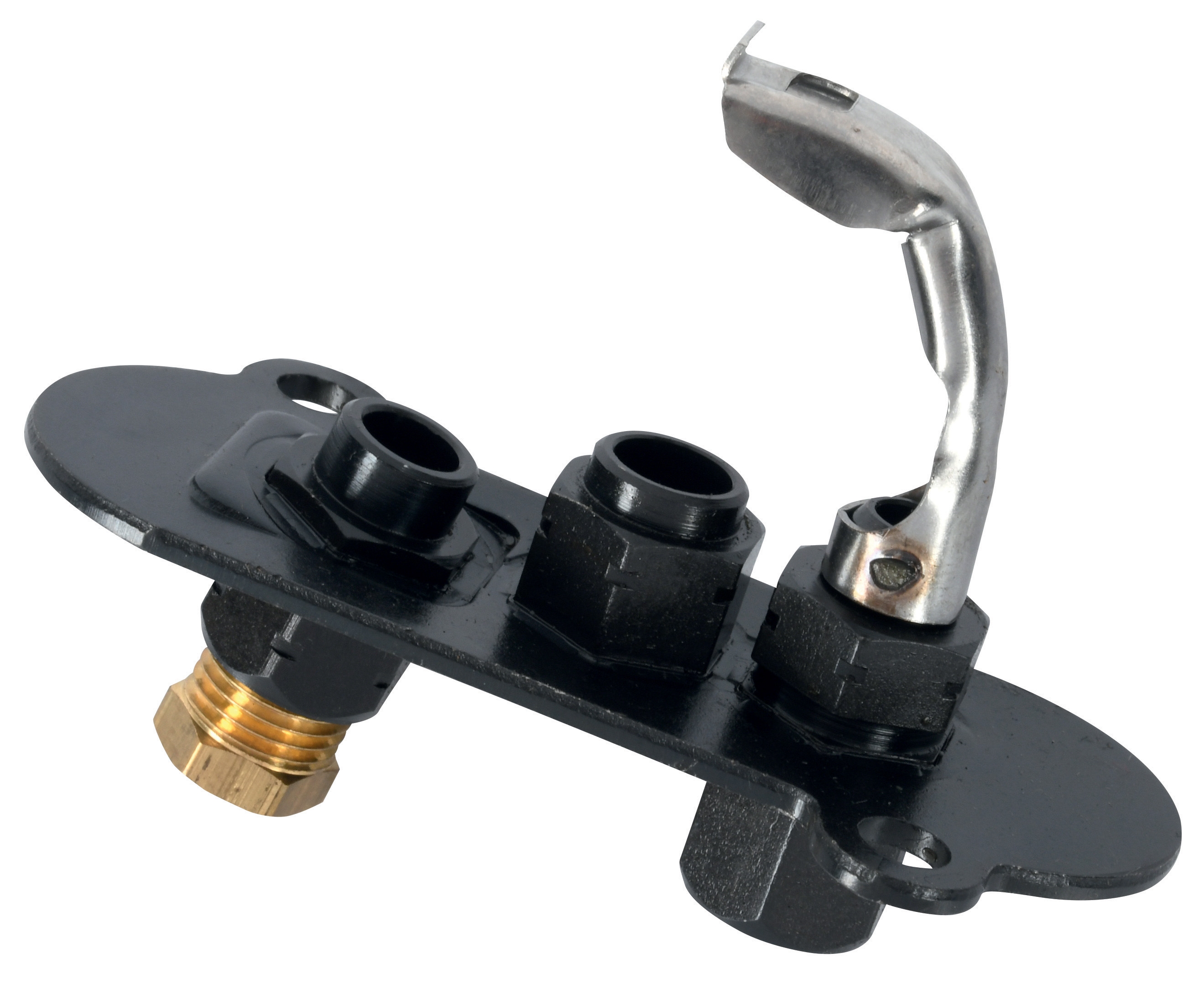
Component selection significantly impacts pilot light system longevity. When replacing pilot burners, select units designed for your specific application profile. SIT pilot-burners designed for intermittent operation (such as the CBM Universal pilot light 1 flame 3 positions, SKU: BLO10268) differ fundamentally from continuous-duty designs in terms of thermal cycling tolerance and internal geometry. The 3-position configuration accommodates varying ignition electrode orientations, providing flexibility for retrofit applications common in Singapore's diverse industrial landscape.
Thermocouple selection requires matching to both the pilot burner model and the control relay specifications. The exclusive use of manufacturer-recommended thermocouples—rather than universal alternatives—is not merely a manufacturer suggestion but a technical requirement. Different burner designs and control systems expect specific thermocouple response characteristics and output voltage ranges. Using mismatched components introduces unnecessary signal uncertainty and increases nuisance shutdowns.
Industrial controls and safety equipment should be sourced from authorized distributors who maintain complete technical documentation. Ensure that replacement components include installation drawings, pressure specifications, and thermocouple recommendations. For complex systems incorporating servo motors (such as the CBM Motor MT 4002 B 2009, SKU: HON47004) for air damper control, maintain detailed records of all component configurations to facilitate future troubleshooting and ensure consistency across multiple unit installations.
Establish preventive maintenance intervals: quarterly visual inspection of electrodes and burner heads, biannual thermocouple continuity testing, and annual replacement of heavily-used components operating in harsh environments. Document all measurements and replacements systematically; trend analysis of thermocouple voltage degradation enables predictive replacement scheduling before failures occur.
Conclusion and Support Resources
Pilot light ignition failures disrupt operations and create safety risks, but systematic diagnostic procedures enable rapid identification and resolution of root causes. Understanding the three primary failure points—ignition electrodes, burner assemblies, and thermocouples—combined with disciplined component testing provides industrial professionals in Singapore with the tools necessary to maintain reliable burner control systems. Equally important is component selection methodology: matching pilot burners and thermocouples to specific burner designs and control systems prevents many failures before they occur in operation.
3G Electric has served Singapore's industrial equipment distribution needs since 1990, maintaining comprehensive inventory of pilot lights, thermocouples, controls and safety components, and specialized burner control equipment. Our technical documentation library includes detailed specifications for all major manufacturer systems, supporting your diagnostic efforts and component selection process. When pilot light troubleshooting requires specialized equipment, technical consultation, or rapid component replacement, contact our team to access expertise and inventory specifically calibrated for Singapore's industrial environment. Reach out to 3G Electric today to discuss your burner control system requirements and optimize reliability across your operations.