Thermocouple and Flame Detection Sensors: Installation and Maintenance Guide for Singapore Industrial Burner Controls
Thermocouples and flame detection sensors form the critical safety backbone of modern industrial burner control systems. These components continuously monitor combustion status and provide real-time feedback to control modules, enabling automatic shutdown if flame loss occurs. For Singapore's industrial facilities operating in high-humidity tropical environments, proper installation and maintenance of these sensors is essential for operational reliability and regulatory compliance. This guide examines the technical principles behind thermocouple operation, flame detection technologies, installation best practices, and maintenance procedures to ensure your burner control system operates safely and efficiently.
Understanding Thermocouple Technology and Flame Detection Principles
Thermocouples operate on the Seebeck effect principle: when two dissimilar metals are joined at a junction and exposed to temperature differences, they generate a small voltage proportional to that temperature difference. In burner control applications, the thermocouple's hot junction sits in the pilot flame, while the cold junction remains at ambient temperature. This voltage differential—typically 0-50 millivolts—is detected by the control relay and converted into a safety signal confirming flame presence.
The most common thermocouple types in industrial burner applications are Type K (chromel-alumel) and Type J (iron-constantan), each with distinct temperature ranges and response characteristics. Type K thermocouples operate reliably from -270°C to 1372°C, making them ideal for pilot burner applications where flame temperatures reach 800-900°C at the ignition electrode.
Flame detection sensors employ three primary detection technologies: ionization electrodes, ultraviolet (UV) sensors, and infrared (IR) sensors. Ionization electrodes measure electrical conductivity in the flame itself—the combustion process creates ionized particles that conduct electrical current between electrodes. UV sensors detect the ultraviolet radiation emitted by hot gases in the flame, typically in the 200-280 nanometer wavelength range. Infrared sensors identify the characteristic radiation signature of flame oscillation, providing rapid response times essential for burner safety interlocks.
Each detection method offers distinct advantages for Singapore's industrial environment. UV sensors provide excellent immunity to ambient light and are particularly effective in outdoor or bright sunlight conditions. Infrared flame oscillation detectors offer superior discrimination against false flame signals from reflected light. The choice between detection technologies depends on your specific burner type, installation location, and environmental conditions.
Thermocouple and Sensor Selection: Technical Specifications and Product Integration
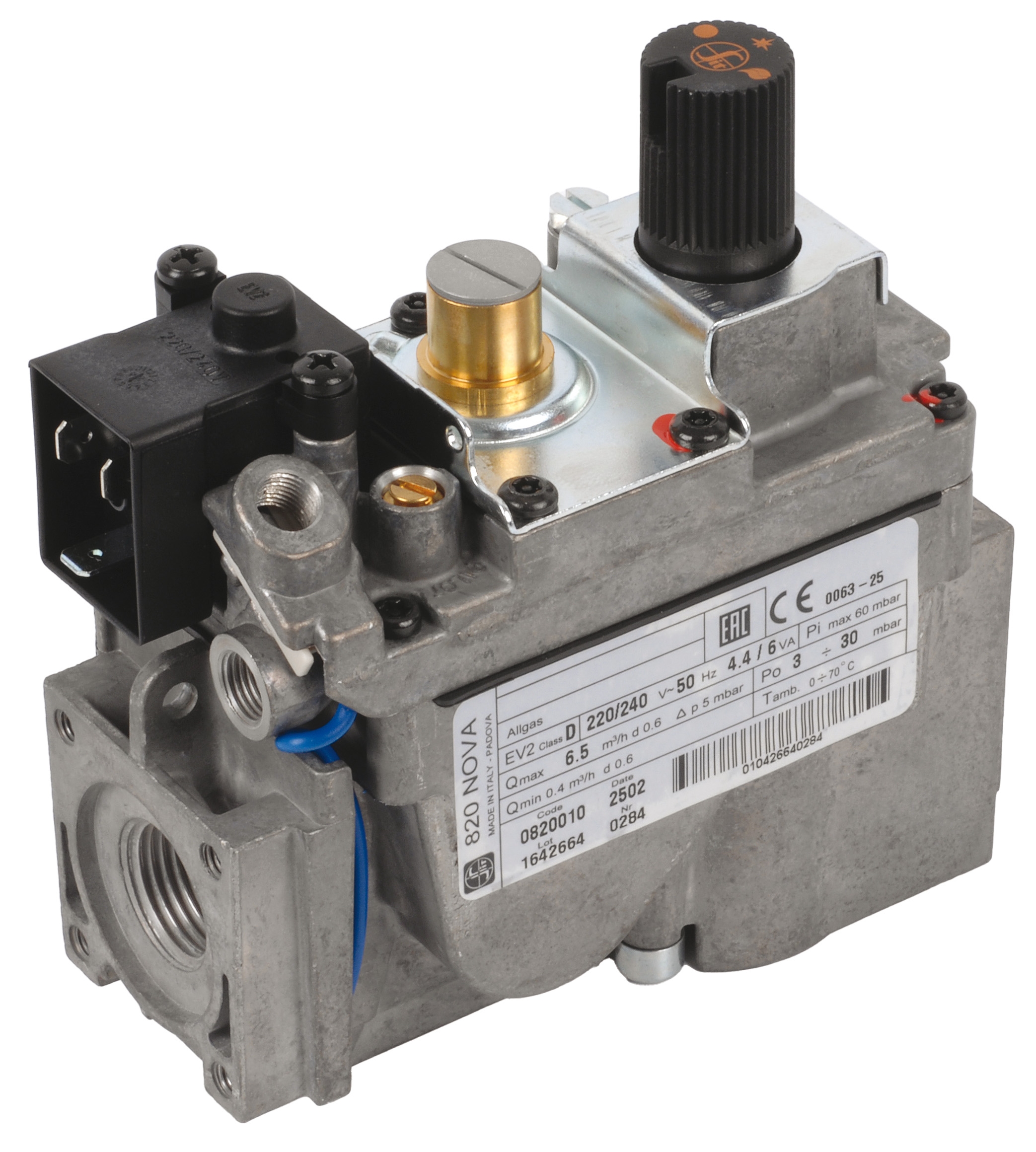
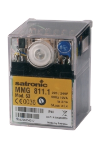
Modern industrial burner control systems, such as the CBM Relay TMG 740-3 63.55, are designed for intermittent-duty gas and mixed-fuel burners with high efficiency ratings. These control modules accommodate multiple flame detection sensor types—ionization electrodes, UV cells, and infrared flame detectors—providing flexibility for various burner configurations and combustion chamber geometries.
Thermocouple selection requires careful attention to flame temperature characteristics and response time requirements. The CBM Thermocouple safety and CBM Sit INT.1000 9x1 0270400 thermocouple represent standard safety-rated thermocouples compatible with pilot burner assemblies. The Q334A pilot burner configuration operates at maximum target tip temperatures of 815°C, requiring thermocouples rated for sustained high-temperature exposure. The Q385A variant operates at 730°C maximum, suitable for applications with lower heat intensity or longer operational cycles.
UV flame detection cells, exemplified by the CBM Cell QRA 10C, provide reliable flame monitoring for Siemens safety control modules and similar systems. These sensors detect ultraviolet radiation in the 200-280nm spectrum emitted by the combustion process, offering response times typically under 1 second. UV cells are particularly advantageous in Singapore's high-ambient-light industrial environments, as they inherently reject visible light interference while maintaining sensitivity to actual flame signatures.
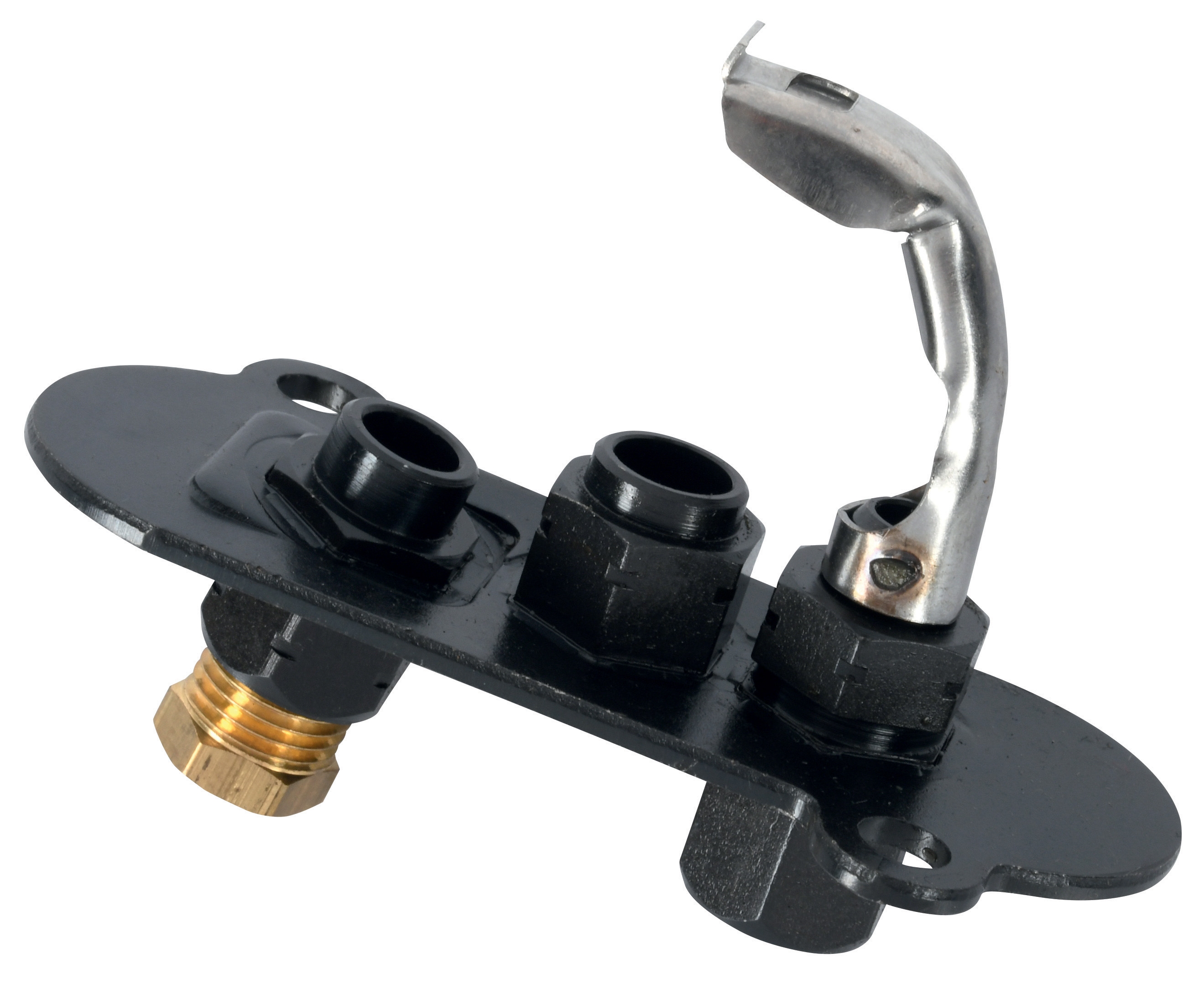
Pilot light assemblies, such as the CBM Universal pilot light 1 flame 3 positions and CBM Pilot light 2 flames 0140015, feature highly-insulated aluminium oxide igniter plugs rated for impact resistance and thermal shock tolerance. These components enable rapid thermocouple substitution and pass rigorous turn-down tests (flame stability across varying gas pressures and combustion air ratios). SIT pilot burners—the standard in this product category—operate with extremely low noise emissions and superior corrosion resistance, critical for tropical industrial environments with high humidity and salt spray exposure.
Control relay bases such as the CBM Base for MA 86 provide mounting infrastructure for servo motors and interface modules. The MT 4000 Series servo motors (exemplified by CBM Motor MT 4002 B 2009, ) deliver 1.5 N·m maximum torque over 90-degree rotation at 6-second cycle times, driving air dampers and butterfly valves in response to control module signals.
Step-by-Step Thermocouple Installation and Flame Detection Setup
Step 1: Pre-Installation Verification
Before beginning installation, verify thermocouple type compatibility with your burner model and control module specification. Confirm the rated temperature ranges exceed your pilot burner's maximum flame temperature by at least 15%. For example, if using a Q334A pilot burner (815°C maximum), select thermocouples rated for minimum 950°C operation. Inspect thermocouples visually for cracks, corrosion, or mechanical damage—damaged units must be replaced before installation.
Step 2: Mounting and Positioning
Position the thermocouple's hot junction directly within the pilot flame, typically 6-12mm from the ignition electrode. The thermocouple should be secured to resist vibration without applying mechanical stress to the junction itself. Use provided thermocouple wells or compression fittings to anchor the sensor while allowing free thermal expansion. Ensure the thermocouple tip does not contact the burner electrode or combustion chamber walls.
Step 3: Electrical Connection and Continuity Testing
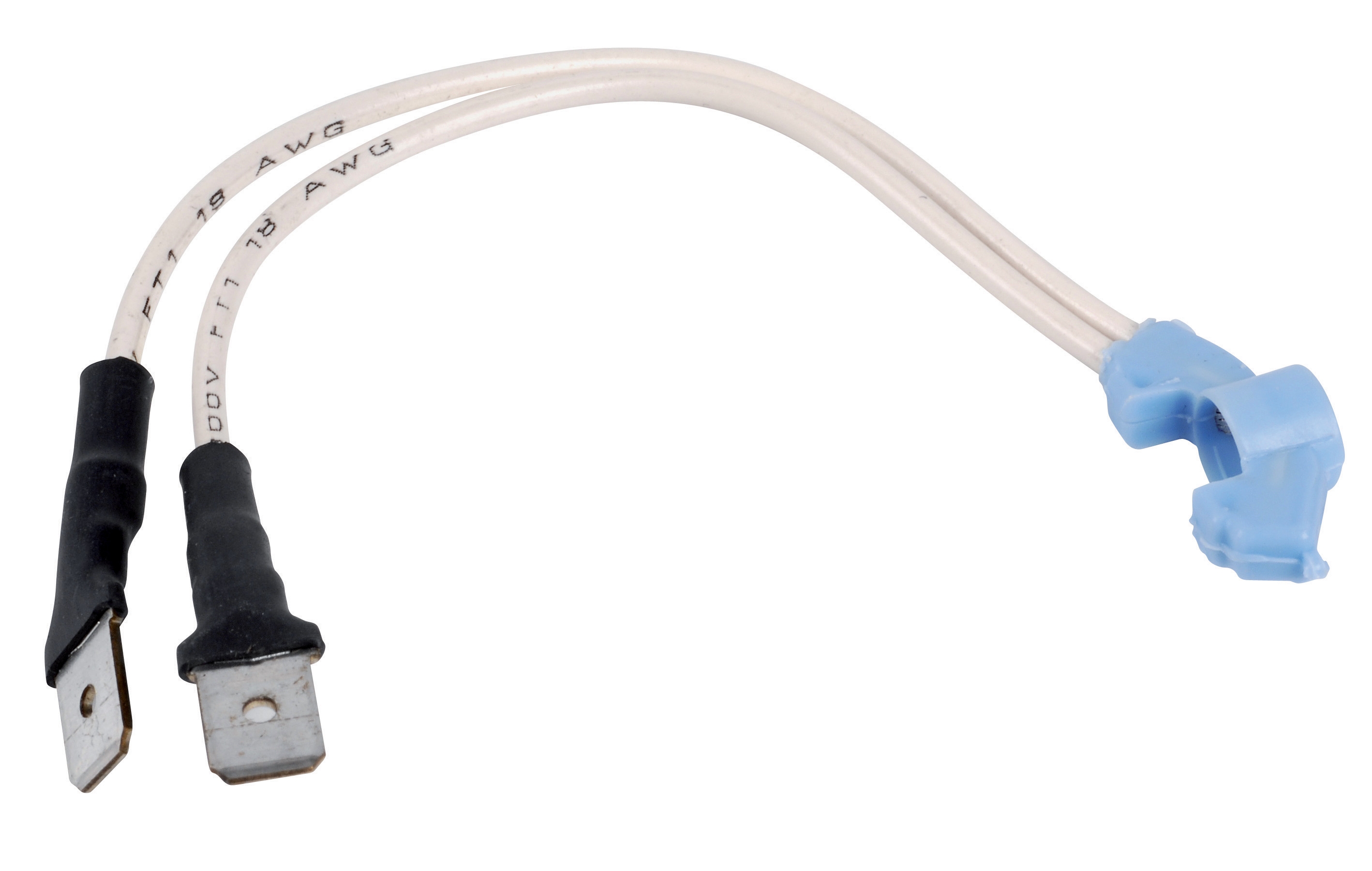
Connect the thermocouple lead wires to the control module's thermocouple terminals, observing correct polarity (positive and negative leads). Use appropriate gauge extension wiring (typically 16-20 AWG for industrial applications) and route leads away from high-voltage electrical circuits and moving mechanical components. Before energizing the system, perform continuity testing with a multimeter to confirm unbroken connections through the entire thermocouple circuit.
Step 4: Flame Detection Sensor Installation
Mount UV or IR flame detection sensors perpendicular to the pilot flame with clear line-of-sight to the combustion process. Position sensors to receive direct flame radiation while minimizing exposure to reflected light from burner chamber walls. Test sensor functionality using manufacturer-provided diagnostic tools or control module built-in self-tests before placing the system in operation.
Step 5: Commissioning and Safety Validation
After 15-20 seconds of normal pilot flame operation, verify that the control module detects stable thermocouple voltage (typically 15-30 millivolts for properly positioned sensors in active flame). Document baseline readings for future reference. Confirm that intentional flame interruption triggers control module shutdown within the manufacturer-specified response time (usually 3-5 seconds). Test flame failure detection by briefly shielding the pilot flame to verify safety interlock operation.
Selection Criteria and Maintenance Best Practices
Selecting appropriate thermocouples and flame detection sensors requires balancing several technical and operational factors. First, match thermocouple type and temperature rating to your specific pilot burner model—mismatched components compromise safety and control reliability. Second, consider your installation environment: Singapore's tropical climate with high humidity and salt spray demands corrosion-resistant materials and proper environmental sealing.
Maintenance procedures directly impact long-term system reliability. Establish quarterly visual inspections of thermocouple and sensor assemblies, looking for discoloration, deposits, or mechanical degradation. Every 12 months, perform detailed continuity and voltage testing to confirm electrical integrity. Replace thermocouples every 3-5 years even if they appear functional—thermocouple metallurgical properties degrade gradually, reducing voltage output and lengthening response times.
For UV and IR flame sensors, clean optical surfaces monthly with soft, lint-free cloths and recommended cleaning solutions. Avoid touching optical surfaces with bare hands, as skin oils degrade sensor sensitivity. Document all maintenance activities in a maintenance log tied to each burner control system; this documentation proves regulatory compliance and supports warranty claims.
When replacing thermocouples, always use manufacturer-recommended components. SIT thermocouples for SIT pilot burners provide optimal thermal matching and response characteristics—substituting alternative brands may void control system certifications. Similarly, keep flame detection sensor models consistent with your control module specifications; mixing UV and IR sensors across a multi-burner installation creates operational inconsistencies and complicates troubleshooting.
Closing and Next Steps
Thermocouple and flame detection sensor installation represents a critical intersection of safety, reliability, and regulatory compliance in industrial burner control systems. Proper component selection, careful installation methodology, and rigorous maintenance procedures ensure your burner control system responds rapidly to combustion anomalies, protecting equipment and personnel throughout your facility's operational life.
Singapore's industrial environment—with year-round high humidity, tropical salt spray, and 24/7 operational demands on many facilities—requires particular attention to sensor corrosion prevention and regular calibration validation. The controls and safety product range available through 3G Electric includes thermocouples, flame detection sensors, and integrated burner control modules specifically selected for tropical industrial applications.
Ready to optimize your burner control system reliability? Contact 3G Electric's technical team to discuss your specific thermocouple and flame detection requirements. Our engineers can recommend appropriate sensor configurations for your burner type, facility environment, and operational profile. With over 30 years serving Singapore's industrial sector, we provide not just products but complete technical support—from initial specification through commissioning and ongoing maintenance. Reach out to 3G Electric today for a consultation with our controls and safety specialists.