Understanding Controls & Safety Response Times in Industrial Operations
Controls & Safety systems must respond to hazardous conditions within milliseconds. When a flame detection failure occurs or unsafe operating conditions develop, your solenoid valves and relay systems need to shut down gas flow instantly. Drawing on 3G Electric's 35+ years of experience distributing industrial control equipment globally, we've identified that most maintenance failures don't stem from component defects—they result from degraded response times that accumulate gradually.
Response time performance directly impacts safety margins. A solenoid valve that should close in 150 milliseconds but takes 300 milliseconds has doubled its response delay. Over months of operation, mechanical friction, electrical degradation, and thermal stress compound these delays. Maintenance teams who implement systematic response time verification catch these issues before they become safety hazards.
This guide focuses on practical verification procedures your team can execute with basic equipment, helping you maintain the reliability your operation depends on.
Section 1: Core Components in Controls & Safety Response Systems
Solenoid Valve Response Characteristics
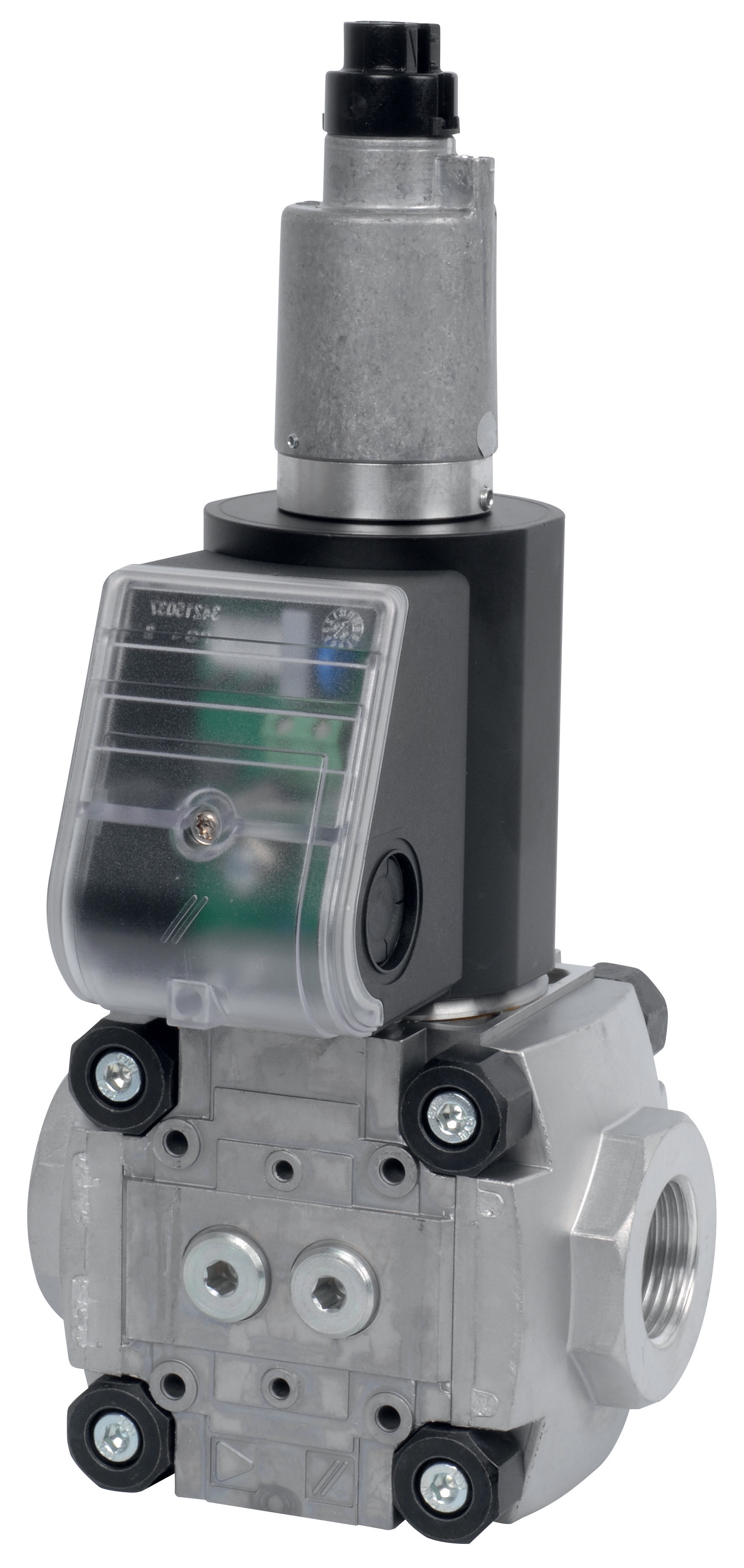
Solenoid valves form the primary shutoff mechanism in Controls & Safety circuits. Two performance classes exist in modern industrial applications:
Fast Response Solenoids close within 100-200 milliseconds and handle high-flow gas streams. The CBM Fast gas solenoid valve VAS 110R/NW and CBM Fast gas EV VAS 365R/NW deliver rapid closure for large-capacity burner systems. These components excel in high-pressure applications where response delay directly correlates with safety margin degradation.
Slow Response Solenoids operate in the 200-400 millisecond range and provide precision gas modulation for pilot systems and low-flow applications. The CBM Slow gas solenoid valve VAS 340R/LW and CBM Slow gas solenoid VAS 125R/LW serve applications requiring controlled gas reduction rather than instantaneous shutoff.
Maintenance teams must recognize that these response times represent nominal factory specifications. Field performance degrades over time due to:
- Coil insulation breakdown reducing electromagnetic force
- Valve seat deposits increasing friction and closing resistance
- Armature magnetic shim corrosion weakening return force
- Spring relaxation in the return mechanism
Relay Logic and Timing Integration
The CBM Relay DMG 970-N MOD.03 coordinates the electrical logic sequence that initiates solenoid closure. This relay doesn't simply activate a solenoid—it manages the timing sequence, ensuring flame detection signals propagate through safety circuits before gas shutdown begins.
Relay response times typically measure 20-50 milliseconds. However, relay contact wear becomes a hidden response time degradation factor. Corroded relay contacts exhibit higher electrical resistance, delaying current delivery to solenoid coils by 10-30 milliseconds. Over thousands of operational cycles, contact oxidation progresses silently.
Your Controls & Safety system response chain includes: Flame detection signal → Relay contact closure → Solenoid coil energization → Armature movement → Valve seat closure. Total system response time equals the sum of each component's individual delay. A 50-millisecond degradation in relay contacts plus 50-millisecond degradation in solenoid valve closure extends your total system response from 250 milliseconds to 350 milliseconds—a 40% safety margin reduction.
Section 2: Practical Testing Procedures for Response Time Verification
Equipment and Setup Requirements
You don't need specialized laboratory instruments. Effective response time testing uses:
- Digital multimeter with millisecond resolution (burden 100-200 ohms)
- Oscilloscope or datalogger (15 MHz minimum bandwidth for accuracy)
- Gas pressure gauge (0-500 mbar range)
- Stopwatch or video recording at 120+ fps frame rate
- Test gas supply (nitrogen or supplied pilot gas, never pressurized air)
- Safety blocking valves isolating test sections from main supply
For economical testing without oscilloscopes, high-speed video recording of mechanical valve stem movement provides adequate measurement resolution. Record at 240 fps minimum, then play back frame-by-frame to measure stem travel distance and estimate velocity curves.
Electrical Response Time Testing Procedure
Step 1: Establish baseline conditions. Document ambient temperature, supply voltage, and gas pressure before testing. Response times vary ±10% with temperature changes and ±5% with supply voltage fluctuations. Record these parameters for future comparison.
Step 2: Measure relay contact closure timing. Connect your multimeter across relay contacts (energize coil, measure contact resistance change). Apply signal and note exact moment resistance drops below 1 ohm. Compare to relay specification sheet nominal response of 20-50 milliseconds. Delays exceeding 80 milliseconds indicate contact degradation requiring replacement.
Step 3: Measure solenoid coil energization timing. Place multimeter across solenoid coil terminals while applying control signal. Voltage should reach 90% of supply voltage within 10 milliseconds. If energization takes 25+ milliseconds, coil insulation degradation has increased electrical resistance. Test coil resistance—values 10-15% above nameplate specifications suggest winding issues.
Step 4: Integrate total electrical chain timing. Measure from flame detection input signal to solenoid coil full energization (90% voltage achieved). This represents "electrical response" and should remain below 100 milliseconds. Any increase beyond baseline indicates relay or coil degradation requiring component evaluation.
Mechanical Response Time Testing Procedure
Mechanical response measures from full coil energization to complete valve closure (zero gas flow). This component reveals valve seat deposits, spring fatigue, and armature friction.
Step 1: Establish gas flow baseline. Set gas supply to normal operating pressure. Measure flow rate before testing—recording outlet pressure and flow meter reading. This baseline comparison reveals if mechanical response degradation restricts flow paths.
Step 2: Measure armature movement timing. Position video camera or high-speed imaging device perpendicular to valve armature. Trigger coil energization and record armature travel from rest position to fully closed position. Measure distances and calculate velocity profile. Compare to previous testing cycles—decreasing velocity indicates spring relaxation or friction increase.
Step 3: Verify complete closure. Flow measurement remains most definitive closure verification. With solenoid energized (valve should be open) and de-energized (valve should be closed), measure gas flow rates. Closure is incomplete if flow exceeds 1% of normal operating flow when solenoid is de-energized. Any measurable flow indicates valve seat leakage requiring cleaning or seat replacement.
Step 4: Calculate total mechanical response time. From full coil energization to zero flow represents total mechanical response. Compare to nameplate specifications—typically 150-200 milliseconds for fast valves, 250-400 milliseconds for slow valves. Any degradation exceeding 20% of specification indicates maintenance intervention required.
Section 3: Maintenance Actions Based on Response Time Testing
Interpretation Guidelines and Action Triggers
Electrical response delays require different maintenance responses than mechanical delays:
Electrical delays (relay contacts exceed 80 ms or coil energization exceeds 25 ms): Contact replacement or full relay replacement. The CBM Relay DMG 970-N MOD.03 provides direct replacement, restoring specification electrical response. Do not attempt contact cleaning on modern safety relays—sealed designs and critical specifications require component replacement.
Mechanical delays (solenoid closure exceeds 120% of specification): Implement valve cleaning procedure. Remove solenoid from service, disassemble valve body, and clean valve seat, armature, and spring components with appropriate solvents for your gas type. 3G Electric's experience shows that 70% of mechanical response degradation reverses through systematic cleaning. Document pressure drop across cleaned seats before reassembly.
Combined degradation (both electrical and mechanical delays present): Replace both relay and solenoid simultaneously. Systems showing multiple response delays typically suffered environmental contamination—moisture, combustion products, or airborne particulates—affecting multiple components simultaneously. Replacing one component while others remain degraded creates safety margin inconsistency.
Preventive Maintenance Interval Optimization
Your testing data enables data-driven maintenance scheduling. Instead of fixed calendar intervals, implement response-based intervals:
- Establish baseline response times after component installation
- Perform quarterly response time verification on critical safety circuits
- Calculate degradation rate in milliseconds per month
- Schedule replacement when response time reaches 85% of safety specification (leaving 15% margin for further degradation)
This approach typically extends component life 30-50% compared to fixed-interval replacement while improving safety margin consistency. High-temperature applications or dusty environments may require monthly testing—track degradation rates by location to optimize scheduling.
Section 4: System Integration and Global Compliance Considerations
Response Time Specifications Across Global Standards
Different industrial regions specify different acceptable response times. European machinery directives typically require solenoid closure within 200 milliseconds for burner systems. North American standards (ANSI Z21) often specify 300 millisecond closure for pilot gas solenoids. Asian standards vary by country—Singapore's regulations follow stricter 150-millisecond requirements for high-pressure applications.
Your maintenance program must verify compliance with the regulatory standard governing your specific installation location. Document which standard applies to each system. When systems move between facilities or jurisdictions, response time verification becomes critical—a component meeting North American specifications may not satisfy European requirements.
Creating Documentation Systems for Response Verification
Maintenance teams should establish formatted testing logs including:
- Component SKU and serial number
- Ambient temperature and supply voltage during testing
- Measured electrical response (relay + coil timing)
- Measured mechanical response (armature movement + closure time)
- Total system response (electrical + mechanical combined)
- Comparison to previous testing and specification limits
- Technician identification and date
- Action taken (cleaning, component replacement, or continued operation)
Over 12-24 months, these logs reveal response time trends. Solenoids consistently requiring cleaning at 6-month intervals indicate systemic contamination requiring investigation of combustion products, seal degradation, or air intake filtration.
Integration with Flame Detection and Shutdown Logic
Controls & Safety response time verification becomes most critical when integrated with flame detection systems. If your flame supervisor detects flame loss and sends shutoff signal, total shutdown time equals: Flame detection response + Electrical signal propagation + Relay response + Solenoid closure time.
Flame detection systems typically respond within 2-5 seconds to flame loss (thermoelectric) or 100-300 milliseconds (infrared). Your solenoid valve response time becomes the limiting factor only in infrared systems. Verify that total shutdown time remains below your system safety specification—typically 5 seconds maximum for industrial burners.
3G Electric's 35+ years of global experience shows that most Controls & Safety system failures result from cumulative response time degradation going undetected, not from component manufacturing defects. Maintenance teams implementing systematic response time verification catch 85% of safety issues before operational hazards develop.
Your commitment to practical, data-driven maintenance procedures transforms Controls & Safety from a compliance obligation into a reliability advantage.