Understanding Controls & Safety in Industrial Operations
Controls & Safety systems form the critical backbone of reliable industrial equipment operation. For maintenance teams managing complex facilities, understanding how these integrated systems function—and more importantly, how to keep them functioning properly—directly impacts operational uptime, worker safety, and equipment longevity.
3G Electric has spent over 35 years distributing industrial equipment globally, and we've learned that most catastrophic control failures don't happen suddenly. They develop gradually through overlooked maintenance intervals, incomplete diagnostic procedures, and reactive rather than preventive approaches. Controls & Safety encompasses everything from solenoid valve operation to pilot light reliability to relay switching accuracy. Each component plays a vital role in the safety chain.
This guide translates technical specifications into actionable maintenance procedures your team can implement immediately, regardless of your facility's geographic location or equipment complexity.
Section 1: Diagnostic Protocols for Controls & Safety Components
Establishing Your Baseline
Before you can maintain Controls & Safety systems effectively, you need to understand what "normal operation" looks like for your specific equipment. Create detailed baseline documentation for each control system:
- Electrical voltage readings at rest and under load (document variance tolerances)
- Solenoid actuation timing from signal to mechanical response
- Pilot light flame appearance and color characteristics
- Relay switching response times in milliseconds
- Safety circuit continuity verification records
Keep these baselines in a searchable maintenance database. When a problem develops, you can compare current readings against your baseline rather than guessing whether something is within acceptable parameters.
Practical Testing Procedures
Solenoid Valve Testing: The double solenoid valve is the workhorse of industrial control systems. CBM VCS 1E25R/25R05NNWL3/PPPP/PPPP double solenoid valve requires systematic testing:
1. Verify electrical supply voltage matches nameplate specifications (±10% tolerance)
2. Listen for the characteristic "click" when energized—absence indicates winding failure
3. Manually actuate the plunger with power OFF to confirm mechanical freedom
4. Test valve ports for proper flow direction using low-pressure air (never assume connections are correct)
5. Document any hesitation or sluggish response as an early warning sign
Solenoid failures typically progress through stages: electrical resistance increase → slower response times → incomplete actuation → complete failure. Catching this progression at stage two or three prevents catastrophic failures.
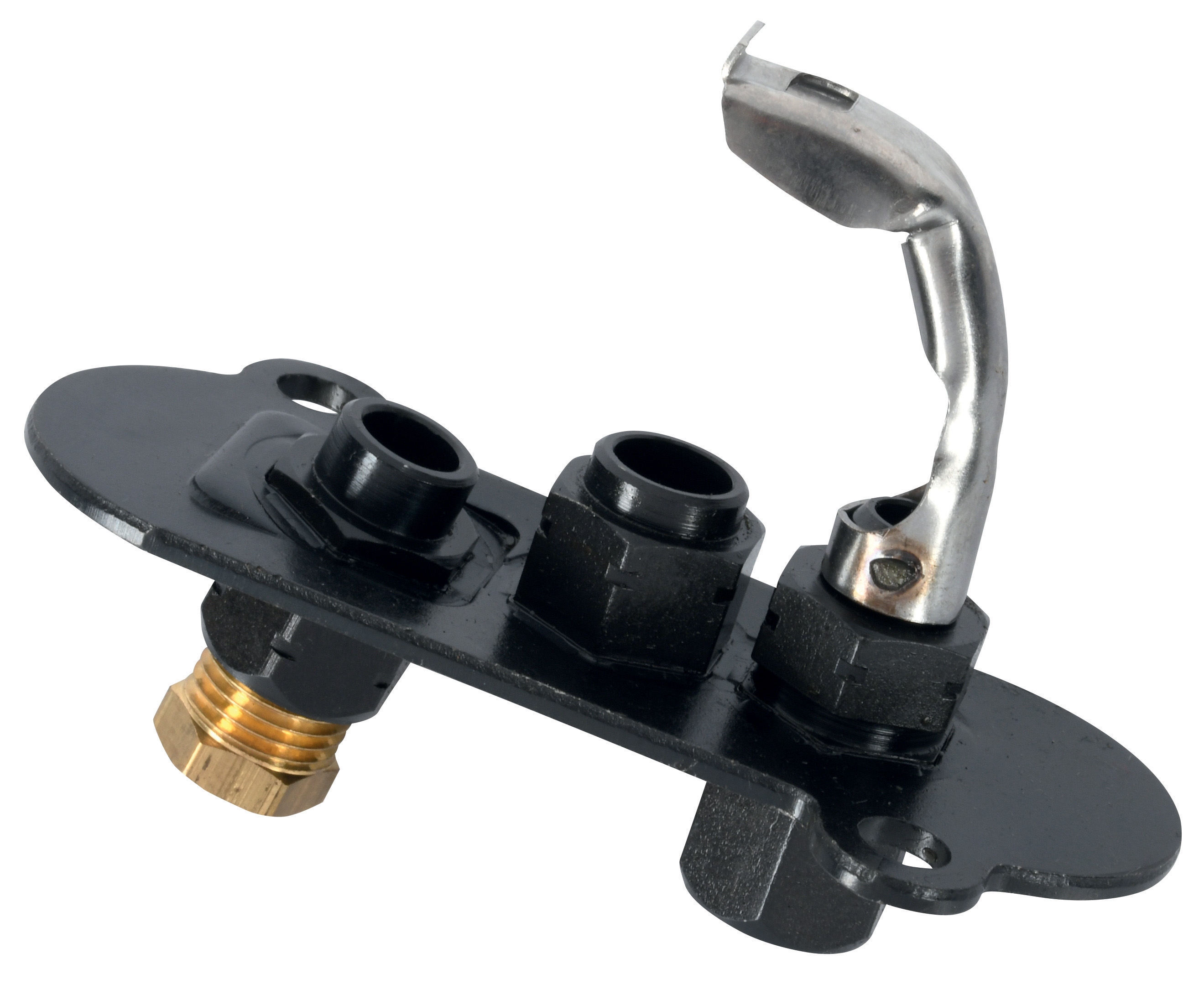
Pilot Light Inspection: Pilot lights like the CBM 1-flame pilot light 0.150.082 and CBM pilot light 1 flame 0140026 are safety-critical components requiring visual inspection during every maintenance cycle:
- Flame should be blue with minimal yellow (indicates complete combustion)
- Flame height should reach the thermocouple tip without engulfing it
- Flame should remain stable without flickering or lifting off the burner
- Any soot accumulation indicates incomplete combustion requiring cleaning
- Test flame stability by gently blowing across the pilot light—proper pilots recover quickly
1. Apply rated voltage to the coil while measuring switching time with a multimeter
2. Verify contact gap distance—worn contacts reduce switching reliability
3. Test both normally-open and normally-closed contact sets
4. Inspect for corrosion or oxidation on contact surfaces (light cleaning with contact cleaner is acceptable)
5. Document switching response time—degradation indicates replacement is imminent
Section 2: Preventive Maintenance Scheduling and Component Lifecycle Management
Monthly Maintenance Tasks
These procedures take 30-45 minutes per system and prevent 80% of common failures:
- Visual inspection of all accessible solenoid valves for leakage or corrosion
- Pilot light flame verification using color and stability criteria
- Electrical connection inspection with visual confirmation of secure terminals and no corrosion
- Dust and debris removal from relay assemblies and control panels
- Safety circuit continuity check using a multimeter on every safety loop
- Documentation entry comparing current observations to baseline readings
Quarterly Deep Maintenance
Every 90 days, expand your maintenance protocol:
- Complete electrical voltage mapping of the entire control system under operating conditions
- Solenoid valve actuation test with timing measurement
- Pilot light thermocouple resistance measurement (typical range 3-12 Ohms—values outside this range indicate replacement)
- Relay coil resistance measurement (compare to nameplate specifications; increases indicate winding degradation)
- Contact gap measurement on all relays using feeler gauges
- Pressure testing of solenoid valves if equipped with pressure ports
- Control system simulation test running through full operating sequence while monitoring all components
Annual Comprehensive Assessment
Once yearly, conduct a complete system evaluation:
- Solenoid valve rebuild or replacement (most manufacturers recommend this at 3-5 year intervals, but annual inspection determines actual need)
- Pilot light assembly removal and cleaning to prevent carbon buildup
- Thermocouple replacement (preventive replacement every 2-3 years prevents thermocouple failure surprises)
- Relay replacement for any units showing resistance increase or sluggish switching
- Complete circuit trace verifying signal path from sensor through safety interlocks to final actuator
- Updated baseline documentation reflecting any component changes or system modifications
Section 3: Troubleshooting Framework for Maintenance Teams
Systematic Problem Isolation
When Controls & Safety systems malfunction, maintenance teams often waste time chasing symptoms rather than root causes. Use this three-step isolation process:
Step 1: Isolate the failure scope. Does the entire control system fail, or only a specific function? If your pilot light won't ignite, that's different from complete power loss. Document exactly what does and doesn't work.
Step 2: Test each component in sequence. Using your baseline data, test the suspected component against known-good values. If the solenoid valve shows no response to electrical input but your multimeter confirms voltage at the coil terminals, the solenoid is failing—not the circuit. If voltage isn't reaching the solenoid, the problem is upstream.
Step 3: Verify the fix. After replacing a component, test that the system functions and returns to baseline performance. This prevents the common mistake of replacing a component and declaring success without confirming the system actually works.
Common Failure Patterns and Solutions
Symptom: No pilot light ignition
Probable causes in order of likelihood:
- Pilot gas supply not reaching the burner (check isolation valve is open)
- Thermocouple connection loose at control module (reconnect firmly)
- Thermocouple resistance exceeds acceptable range (measure with multimeter; if >15 Ohms, replace)
- Pilot light assembly obstructed by soot (remove and clean carefully)
- Gas supply contaminated with moisture (bleed supply line)
Probable causes in order of likelihood:
- Loose electrical connections vibrating under operation (inspect and secure all terminals)
- Relay contact corrosion causing intermittent switching (clean contacts or replace relay)
- Power supply voltage fluctuating beyond ±10% tolerance (test with multimeter during operation)
- Safety circuit nuisance trips (review interlocks for proper function)
- Solenoid coil resistance increasing due to moisture ingress (measure resistance; if trending up, schedule replacement)
Probable causes in order of likelihood:
- Solenoid coil winding partially degraded (measure resistance; expect 15-50 Ohms depending on voltage rating)
- Valve internal passages partially blocked (apply compressed air from opposite port to clear)
- Plunger mechanical binding (remove valve if safe and verify plunger moves freely)
- Supply voltage below specifications (confirm line voltage with multimeter)
- Internal valve wear allowing leakage (if air bleed doesn't solve, schedule valve rebuilding)
Section 4: Building a Sustainable Controls & Safety Program
Documentation as Your Maintenance Foundation
Maintenance teams with strong documentation programs catch problems 60% earlier than reactive teams. Create standardized forms capturing:
- Component identification (manufacturer, model, serial number, date installed)
- Baseline readings (voltage, resistance, timing, pressure)
- Current readings (same measurements, recorded quarterly)
- Trend notes (are values degrading predictably?)
- Service history (what was replaced, when, and why?)
- Next scheduled action (when should this component be retested or replaced?)
Simple spreadsheets work fine—don't overcomplicate this. The goal is capturing enough data to spot trends before components fail.
Training Your Team
Controls & Safety maintenance requires understanding both electrical principles and mechanical operation. Ensure your team receives hands-on training on:
- Safe isolation procedures before any maintenance
- Proper multimeter use and measurement interpretation
- How to read and verify component specifications
- Safe procedures for working with pressurized systems
- When to call a specialist versus handling in-house
Supplier Partnership for Long-Term Support
3G Electric's 35+ years in industrial equipment distribution means we understand that maintenance teams need reliable access to components when you need them. Partner with suppliers who:
- Stock the exact replacement components for your installed equipment
- Provide technical specifications and wiring diagrams without delays
- Support your training with technical resources
- Can quickly ship emergency replacement parts
- Understand that downtime costs far exceed component costs
Conclusion
Controls & Safety systems are too critical for guesswork. By implementing systematic diagnostics, preventive maintenance scheduling, and documented troubleshooting procedures, maintenance teams transform controls from a source of surprise failures into a predictable, manageable system requiring routine care.
The investment in time learning these procedures pays dividends through reduced downtime, improved safety records, and longer component lifecycles. Start with one control system, document your baseline, and expand your program methodically. Within six months, you'll have the data and procedures needed to manage Controls & Safety with confidence.
