Understanding Burners & Combustion System Reliability
Burners & combustion systems form the thermal backbone of countless industrial processes—from food processing and textile manufacturing to pharmaceutical production and chemical processing. Yet despite their critical role, many maintenance teams approach these systems reactively rather than strategically. With over 35 years of experience distributing industrial equipment globally, 3G Electric has observed that the difference between high-performing and problematic combustion systems often comes down to one factor: systematic preventive maintenance of control components.
The combustion process itself is straightforward chemistry. Fuel, air, and ignition create controlled thermal energy. What separates reliable operations from costly failures is the precision of control systems governing that reaction. Solenoid valves, relays, and safety interlocks must function with metronomic consistency. A single valve malfunction doesn't just reduce efficiency—it can trigger cascading failures, safety shutdowns, and extended downtime.
This guide addresses the maintenance reality facing global operations: how to establish sustainable preventive maintenance protocols that keep burners & combustion systems operating at peak efficiency while minimizing emergency interventions.
Solenoid Valve Management: The Foundation of Combustion Control
Identifying Your Valve Configuration Requirements
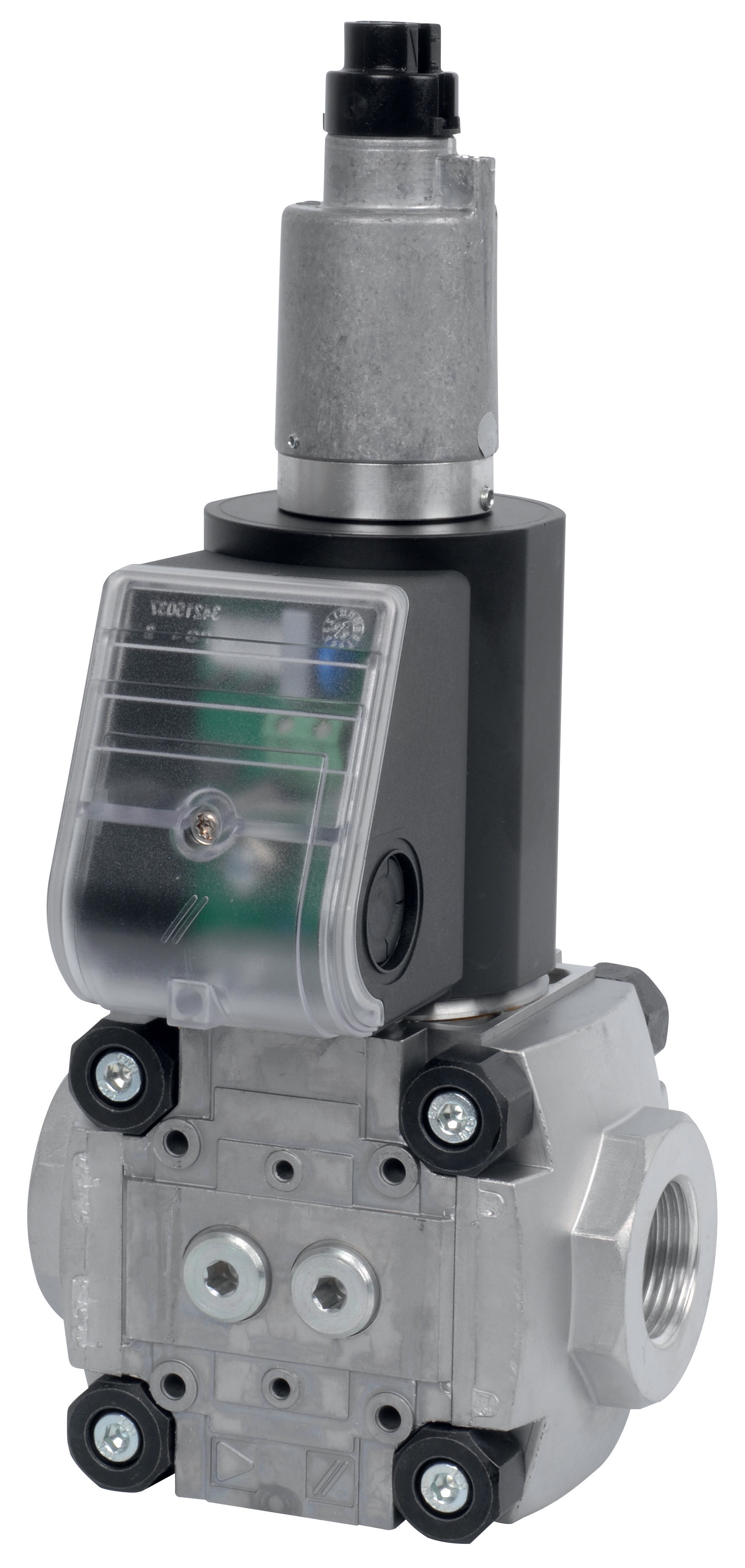
Solenoid valves are the gatekeepers of fuel flow in modern burners & combustion systems. Understanding which valve type your system requires is foundational to effective maintenance planning. Industrial burners typically employ two distinct valve technologies: slow-acting (modulating) valves and fast-acting (safety shutoff) valves.
Slow-acting solenoid valves like the CBM Slow gas solenoid valve VAS 340R/LW and CBM Slow gas solenoid VAS 125R/LW are designed for modulation applications. These valves control fuel flow rate proportionally, enabling gradual adjustments to flame intensity and thermal output. They operate with response times measured in hundreds of milliseconds, allowing smooth transitions as load demands change. Maintenance teams should understand that these valves maintain internal hydraulic balancing mechanisms that require periodic verification.
Fast-acting safety valves such as the CBM Fast gas solenoid valve VAS 110R/NW and CBM Fast gas EV VAS 365R/NW provide critical safety functions. These rapid-response valves (typically 80-150ms response time) shut off fuel supply during flame failure, loss of air, or combustion control signal loss. They're not designed for modulation but for binary operation—open or closed—with absolute reliability.
A fundamental maintenance error occurs when teams treat all solenoid valves identically. Slow-acting modulating valves require different inspection intervals and cleaning protocols than safety shutoff valves. Understanding your specific valve application determines your preventive maintenance strategy.
Preventive Maintenance Protocols for Solenoid Valve Performance
Quarterly Inspection Schedule:
- Visual inspection of valve body for corrosion, carbon deposits, or fuel weeping
- Electrical coil resistance measurement (should remain within manufacturer specifications)
- Listening test during operation (solenoid should click distinctly during energization)
- Documentation of response characteristics and any hesitation in valve opening/closing
- Remove valve from circuit and perform bench testing with clean fuel at rated pressure
- Inspect internal orifices for carbon buildup or particle contamination using magnification
- Verify plunger movement is smooth without stiction or binding
- Clean or replace fuel inlet strainers ahead of valves
- Test coil insulation resistance (minimum 10 megohms for safety-critical applications)
- Complete valve disassembly and inspection of seals, springs, and internal components
- Replacement of deteriorated seals and springs per manufacturer specifications
- Ultrasonic cleaning of all internal passages
- Pressure testing at 150% of rated operating pressure
- Reassembly with documented torque specifications
This structured approach prevents the gradual degradation that leads to unpredictable valve performance. Teams using this protocol consistently report 40-60% reductions in combustion-related shutdowns.
Relay and Control System Integration Maintenance
The CBM Relay DMG 970-N MOD.03 represents a common control relay found in burners & combustion ignition and safety circuits. These relays orchestrate the sequence of solenoid valve energization, fuel pump operation, and ignition system timing. Relay failures often manifest as intermittent combustion starts, false flame failures, or inability to achieve stable flame.
Relay Diagnostics and Maintenance
Visual Inspection Points:
- Examine contacts for oxidation (green patina), pitting, or welding
- Check for loose terminal connections or corroded wire ferrules
- Inspect relay case for cracks, heat damage, or moisture ingress
- Verify mounting position is stable and isolated from vibration sources
- Using a multimeter, measure coil resistance (should match nameplate specifications)
- Apply rated voltage and verify distinct audible click during energization
- Using a continuity tester, verify contact closure during energization and opening during de-energization
- Document switching time if precision timing is critical to your application
- Test with slightly reduced voltage (85-90% nominal) to verify pick-up and drop-out thresholds
- Install protective surge suppression (diodes or varistors) across relay coils to prevent contact damage from voltage spikes
- Maintain relay location temperature between 5-40°C; extremes accelerate contact deterioration
- Ensure adequate ventilation around relay enclosures to prevent dust accumulation on contacts
- Implement contact conditioning—occasional light arcing during normal operation actually helps maintain contact surfaces
Relays operating in combustion control circuits should be evaluated for replacement every 3-5 years even if functioning adequately. The cost of preventive relay replacement is negligible compared to unplanned downtime from a failed ignition sequence.
Integrated System Maintenance Strategy
Establishing a Combustion System Maintenance Calendar
Effective maintenance requires integration of all component monitoring into a coordinated schedule. Rather than maintaining individual components, high-performing operations establish system-level maintenance windows.
Monthly Checks:
- Verify all solenoid valve coils are energizing properly
- Check fuel pressure at valve inlet (should remain within ±5% of setpoint)
- Inspect flame quality visually or via flame sensor signal strength
- Document any irregularities in startup sequence timing
- Clean or replace fuel system strainers
- Perform solenoid valve electrical testing as described above
- Verify relay contact integrity through switching cycles
- Check all cable connections for vibration-induced loosening
- Inspect burner tile and refractory for cracks or degradation
- Schedule bench testing of critical solenoid valves
- Complete relay contact cleaning or replacement
- Perform combustion analysis testing (CO2, O2, NOx levels)
- Verify all safety interlocks respond correctly
- Review maintenance logs for trending patterns
- Remove and completely service all solenoid valves
- Replace all critical seals and springs
- Perform complete relay testing and contact burnishing
- Professional combustion system tuning
- Update control logic parameters based on observed performance
Documentation and Performance Tracking
Maintenance data becomes actionable intelligence when systematically tracked. Establish a simple database recording:
- Solenoid valve operational hours and switch cycles
- Fuel pressure readings at each service interval
- Combustion efficiency test results
- Relay coil resistance measurements
- Any anomalies or hesitations in system response
Trending this data reveals degradation patterns. For example, gradually increasing solenoid response time typically indicates internal carbon buildup—an early warning sign allowing planned maintenance before failure. Rising relay coil resistance may suggest thermal stress or moisture ingress, warranting relay replacement before catastrophic failure.
Global Considerations and Regional Adaptations
With 35 years of global distribution experience, 3G Electric understands that burners & combustion maintenance must adapt to regional conditions.
High-Humidity Environments (Southeast Asia, Gulf Coast regions):
- Increase relay inspection frequency to quarterly due to moisture-accelerated contact corrosion
- Implement silica gel desiccant packs in control enclosures
- Specify stainless steel solenoid valve bodies for corrosion resistance
- Plan more frequent coil insulation resistance testing
- Employ vibration-isolating relay mounts
- Increase electrical connection torque specifications to prevent micro-vibrations
- Plan semi-annual rather than annual relay replacement cycles
- Specify reinforced solenoid valve manifold mounting
- Implement upstream fuel filtering with 10-micron screens ahead of solenoid valves
- Establish monthly strainer cleaning schedules rather than quarterly
- Perform quarterly bench testing of solenoid valves in regions with inconsistent fuel supply
- Consider redundant safety shutoff valves in mission-critical applications
- Pre-burner fuel heaters prevent fuel viscosity issues affecting solenoid valve response
- Winter maintenance plans should include coil insulation resistance testing (cold stress increases failures)
- Ensure solenoid valve coils are rated for ambient operating temperatures
- Verify relay contact materials remain conductive at minimum operating temperatures
Implementation Roadmap for Maintenance Teams
Transitioning to systematic preventive maintenance requires staged implementation:
Phase 1 (Month 1-2): Audit and Documentation
- Document all solenoid valve specifications, installation dates, and operating hours
- Photograph and record current relay installations
- Establish baseline combustion efficiency measurements
- Create maintenance logbooks for each burner system
- Perform complete solenoid valve bench testing on all units
- Clean or replace all fuel system strainers
- Condition relay contacts through multiple switching cycles
- Establish electrical measurement baselines (coil resistance, insulation, contact voltage drop)
- Implement monthly inspection routines
- Execute quarterly solenoid valve electrical testing
- Conduct semi-annual relay contact assessments
- Track all measurements in consolidated database
- Adjust intervals based on performance trends
Maintenance teams implementing this three-phase approach typically achieve:
- 35-50% reduction in combustion-related emergency shutdowns
- 25-40% improvement in mean time between failures
- 20-30% reduction in maintenance labor costs through planned versus reactive work
- Improved regulatory compliance documentation for safety-critical applications
Conclusion
Burners & combustion system reliability is not mysterious—it's the direct result of systematic component maintenance executed with precision and consistency. Solenoid valves and control relays don't fail suddenly; they degrade gradually through use, contamination, and environmental stress. By implementing the preventive protocols outlined above, maintenance teams can transform these critical systems from sources of unpredictable downtime into dependable process components.
3G Electric's 35+ years of global industrial equipment distribution has reinforced one consistent lesson: the most successful maintenance operations are those that shift from reactive emergency repairs to proactive component management. The investment in systematic preventive maintenance of burners & combustion control components yields returns not just in reduced downtime, but in operational peace of mind and regulatory compliance assurance.
Your solenoid valves and control relays are tools like any other—their performance depends on how you use and maintain them. Apply the protocols in this guide, track your results, and adjust based on actual performance data. The maintenance teams that embrace this approach build industrial operations of genuine reliability.