Introduction: Moving Beyond Reactive Maintenance
Traditional maintenance approaches treat burners & combustion systems as "run-to-failure" assets. Maintenance teams react only after performance drops, efficiency plummets, or catastrophic failure occurs. In Southeast Asia's demanding industrial environment—with high humidity, temperature fluctuations, and 24/7 operational demands—this reactive posture costs thousands in unplanned downtime, energy waste, and emergency repairs.
Predictive maintenance flips this model. By establishing baseline performance metrics, monitoring key indicators, and recognizing early degradation signs, your team can schedule maintenance during planned shutdowns, order replacement parts in advance, and maintain optimal combustion efficiency year-round. Drawing on 35+ years of experience as a distributor of industrial equipment, 3G Electric has supported countless maintenance teams across Southeast Asia in transitioning to condition-based strategies that directly improve uptime and reduce total cost of ownership.
This guide provides actionable protocols for monitoring burners & combustion systems, interpreting diagnostic signals, and building a sustainable maintenance calendar that keeps equipment running reliably.
Section 1: Establishing Performance Baselines & Key Monitoring Parameters
Why Baselines Matter
You cannot detect degradation without knowing what "healthy" looks like. The first step in any predictive maintenance program is documenting baseline performance under normal operating conditions. This baseline becomes your reference point for all future diagnostics.
For burners & combustion systems, critical baseline parameters include:
- Flame signal strength: UV and IR flame detectors produce electrical signals proportional to flame intensity. A healthy system should maintain consistent signal levels across startup, steady-state, and modulation cycles.
- Combustion efficiency: Stack gas temperature, O₂ content, and CO₂ concentration indicate how completely fuel burns. Baseline values vary by fuel type and burner design.
- Pressure differential: Draft pressure across the firebox, air supply pressure, and fuel pressure should remain stable under constant load.
- Temperature rise: The temperature increase across the heat exchanger reflects thermal transfer efficiency.
- Ignition delay time: The period between spark initiation and flame establishment should be consistent—extended delay suggests electrode fouling or fuel delivery problems.
Capturing Baseline Data
During initial commissioning or when equipment is known to be in peak condition, record these measurements:
1. Optical & electrical signals: Use a multimeter to measure flame detector output voltage. For UV flame detection cells like the Combutech UV1p detection cell, typical signal strength ranges from 0.5–5 V depending on flame distance and intensity. Document this under standard load.
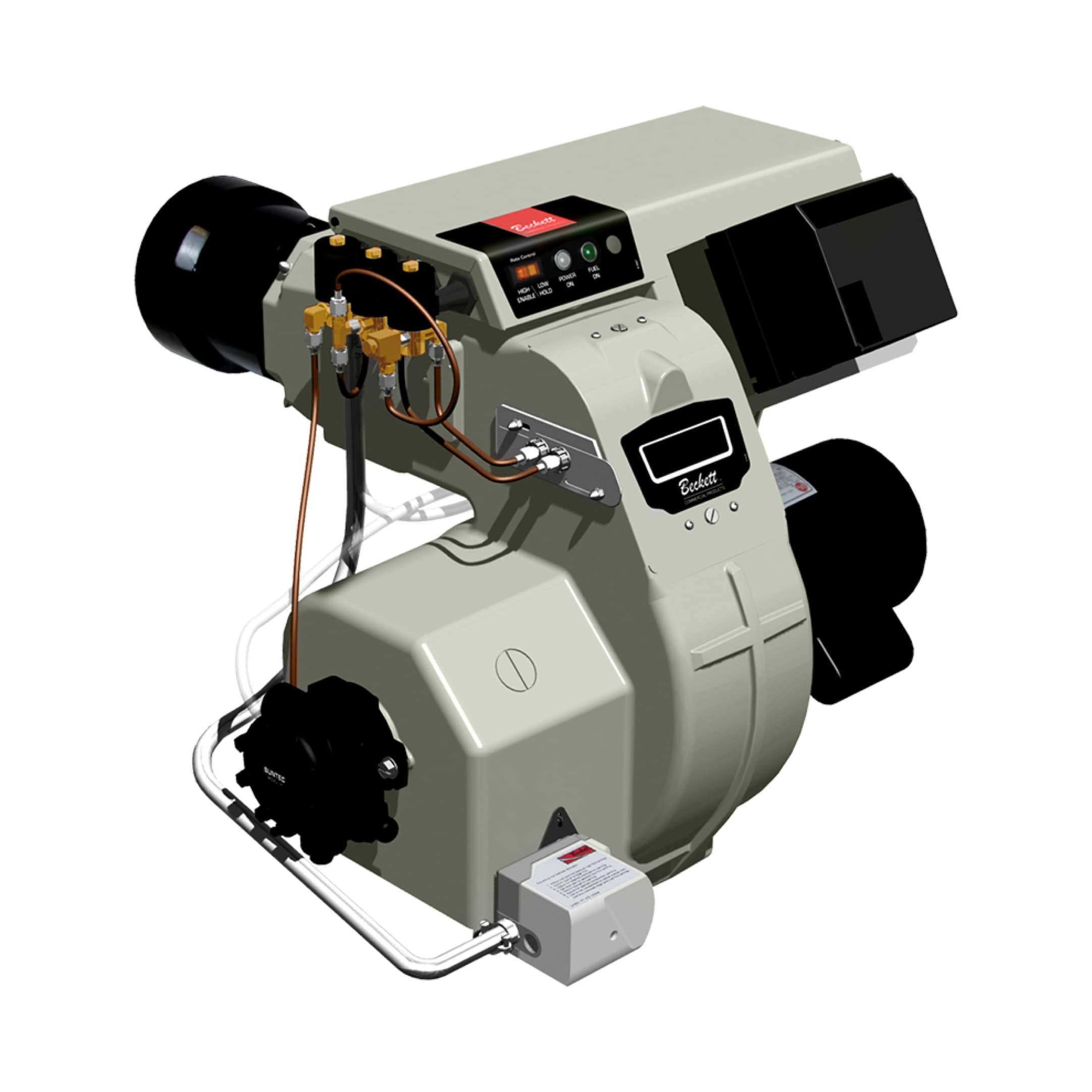
2. Fuel flow rate: Measure actual fuel consumption (GPH for oil burners like the Beckett CF3500 Oil Burner, or kg/h for gas burners) and compare against nameplate ratings to verify spray pattern efficiency.
3. Air/fuel ratio: Use portable combustion analyzers to measure stack gas composition. For most applications, target 3–8% O₂ in exhaust; higher values indicate incomplete combustion.
4. Acoustic signature: Modern burners produce characteristic noise patterns. Record baseline sound levels during normal operation using a simple sound meter—unexpected noise often precedes mechanical failure.
5. Vibration baseline: If equipment has forced draft fans or fuel pumps, establish vibration baseline using a portable analyzer. Increasing vibration indicates bearing wear or imbalance.
Documentation Protocol
Create a maintenance logbook (digital or physical) recording:
- Date, time, and ambient conditions
- Load percentage and duration
- All measured parameters
- Technician name and signature
- Equipment serial number and age
Repeat baseline capture quarterly for the first year of operation. This establishes seasonal patterns and clarifies normal variation from true degradation.
Section 2: Real-Time Monitoring & Early Degradation Detection
Flame Detection as a Diagnostic Tool
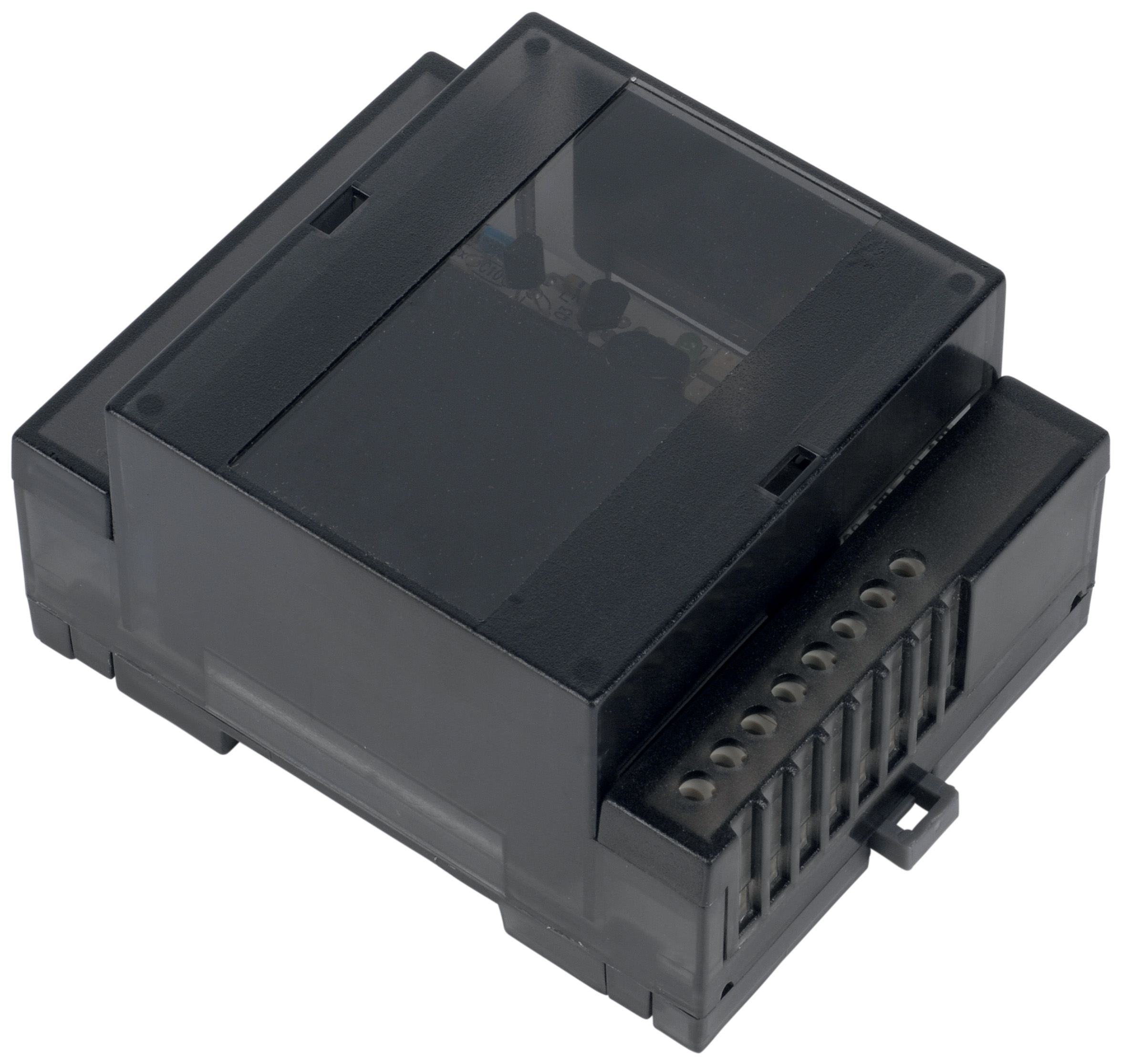
Flame detection systems do more than confirm ignition—they provide continuous feedback on combustion health. The Combutech Flame relay CF1 is a control module that monitors multiple UV detectors (up to 10) and converts flame signals into electrical outputs for programmable logic controllers or burner management systems.
What declining flame signal means:
- Gradual signal reduction (10–20% drop over weeks) typically indicates fouling: oil mist accumulation on UV detector windows, soot buildup on combustion chamber walls, or mineral deposits on optical surfaces.
- Sudden signal loss suggests flame blowout, air inlet blockage, fuel delivery failure, or electrode misalignment.
- Unstable, fluctuating signals indicate incomplete combustion, draft instability, or fuel pressure oscillation.
1. Establish signal voltage baseline at commissioning.
2. Record flame signal voltage weekly during routine inspections.
3. Alert maintenance when signal drops below 70% of baseline.
4. Schedule cleaning when signal falls to 50–60%.
5. Investigate immediately if signal fluctuates >±20% during steady-state operation.
Combustion Efficiency Trending
Stack gas analysis reveals how fuel burns. Conduct quarterly combustion tests using portable analyzers that measure O₂, CO₂, CO, and NOx.
Troubleshooting signals from combustion analysis:
| Finding | Likely Cause | Action |
|---------|-------------|--------|
| Rising O₂ (excess air) | Air inlet fouling, damper misalignment, fuel nozzle wear | Clean air inlet, verify draft settings, inspect nozzle |
| Increasing CO | Incomplete combustion, fuel delivery problem, flame temperature too low | Check fuel atomization, verify combustion air supply, test ignition timing |
| Declining CO₂ | Air leak into combustion chamber, flame recession, fuel system issue | Inspect firebox gaskets, adjust air registers, verify fuel pressure |
| Rising stack temperature | Heat exchanger fouling, reduced airflow, scale buildup | Schedule cleaning, check fan operation, inspect tubes/passages |
Temperature Trending & Heat Exchanger Fouling Detection
Maintain a log of stack temperature (measured at flue exit) and inlet/outlet temperatures. For systems with process loops, track process fluid outlet temperature.
Heat exchanger degradation indicators:
- Stack temperature rising while fuel consumption unchanged → fouling inside heat exchanger
- Process outlet temperature declining → reduced heat transfer (fouling or circulation problem)
- Temperature rise inconsistent with load → airflow imbalance or blocked passages
For Southeast Asian facilities with high humidity and salt-air environments, soot and scale accumulation accelerates. Establish quarterly cleaning schedules for heat exchangers; increase to monthly in coastal locations or heavily loaded systems.
Pressure & Draft Monitoring
For forced-draft burners (like the FBR HI-GAS P550/M CE TL high-capacity industrial gas burner), establish draft pressure baselines:
- Burner firing pressure: Should be stable and proportional to load.
- Furnace draft: Typically –0.05 to –0.20 inches water column; increasing demand indicates blockage or fan wear.
- Fuel pressure: Oil burners should maintain consistent supply pressure; fluctuation suggests pump cavitation or fuel line restriction.
Rising draft pressure demand (same load, higher pressure needed) indicates:
- Fan impeller fouling
- Inlet air filter restriction
- Furnace tube or passage blockage
Schedule fan cleaning or filter replacement when draft pressure rises 20% above baseline.
Section 3: Component-Level Condition Assessment & Remaining Life Estimation
Fuel Nozzle & Atomization Integrity
Fuel nozzles degrade through oxidation, carbon deposit, and mechanical wear. For the Beckett CF3500 Oil Burner (17–35 GPH range), nozzle condition directly affects spray pattern, combustion efficiency, and flame stability.
Visual inspection protocol:
1. Shut down burner and allow cooling (minimum 30 minutes).
2. Remove nozzle and examine orifice using magnification (10×).
3. Look for:
- Carbon deposits or varnish (indicates oxidized fuel residue)
- Irregular orifice shape (erosion or crystalline buildup)
- Oil weeping at nozzle body seams (seal degradation)
Condition-based replacement:
- Stage 1 (Baseline): Clean spray pattern, no visible deposits → Plan replacement at 2-year interval.
- Stage 2 (Early degradation): Light carbon coating, slight spray asymmetry → Clean or replace within 6 months.
- Stage 3 (Advanced degradation): Heavy deposits, spray pattern irregular, CO or O₂ abnormal → Replace immediately.
UV Flame Detector Optical Condition
The Combutech UV1p detection cell (IP65 rated, spectral response 185–260 nm) is highly sensitive to optical fouling. Soot, oil mist, and mineral deposits on the sensor window cause signal loss that mimics actual flame problems.
Detector maintenance schedule:
- Monthly: Visual inspection through burner door (where visible) for window fouling.
- Quarterly: Remove detector, wipe external window with lint-free cloth and appropriate solvent (isopropyl alcohol for most deposits).
- Semi-annually: Inspect ceramic insulator for cracks; check connector pins for corrosion.
- Annually: Consider factory recalibration if available; compare actual signal voltage to commissioning baseline.
Air Intake Filter & Draft System Assessment
Clogged air intake filters are the leading cause of combustion degradation in Southeast Asian installations, where dust, salt spray, and humidity create rapid accumulation.
Inspection frequency:
- Weekly in high-dust environments (cement, food processing, coastal facilities): Visual check of filter media for saturation.
- Monthly in standard industrial settings: Measure draft pressure upstream and downstream of filter. When differential exceeds manufacturer spec (typically 0.3–0.5 inches WC), clean or replace filter.
- Quarterly in clean environments: Standard inspection.
Ignition Transformer & Electrode System
Direct spark ignition systems (as on the Beckett CF3500) require reliable high-voltage spark. Electrode degradation occurs through oxidation, corrosion, and gap erosion.
Condition assessment:
1. Visual inspection: Remove electrode assembly and examine for:
- Corrosion (greenish/white coating on copper contacts)
- Electrode tip erosion (rounded instead of sharp)
- Carbon tracking (black conductive paths on ceramic insulator)
2. Spark quality test: With ignition energized (safety: ensure fuel shut off), observe spark color and intensity. Weak, orange, or intermittent sparks indicate transformer degradation or high-voltage leakage through contaminated insulators.
3. Gap measurement: Correct electrode gap is critical (typically 0.150–0.175 inches for oil burners). Widening gap due to electrode erosion increases ignition delay and misfire risk.
Maintenance intervals:
- Clean electrodes and ceramic insulators quarterly with isopropyl alcohol and compressed air.
- Reset/adjust gap to specification when gap measures >0.020 inches beyond nominal.
- Replace electrodes when gap reaches 0.200+ inches or spark quality is visibly weak.
- Replace ignition transformer if no spark occurs despite fresh electrodes and correct gap.
Gas Burner Nozzle & Mixing Head Assessment (Progressive/Modulating Systems)
For gas burners like the FBR GAS/M CE D2"S-F-50 (progressive modulation, 485–4070 kW range), the nozzle and mixing head require periodic inspection to maintain combustion stability across load ranges.
Condition check:
1. Visual: Inspect mixing head bore for carbon deposits or metal discoloration (sign of excessive temperature).
2. Gas pressure test: Verify fuel pressure at nozzle under full load (should match nameplate spec, typically 2.5–4.0 bar for industrial gas burners).
3. Flame pattern observation: At low, medium, and full load, flame should be stable with no lift-off, delay, or unusual color/noise.
4. NOx emissions trend: If monitored, rising NOx indicates higher combustion temperature (burner creeping hotter); often caused by air inlet restriction or gas supply pressure drift.
Preventive actions:
- Clean nozzle bore with appropriate soft brush or compressed air quarterly.
- Verify gas supply pressure weekly; install pressure gauge and trending log if not present.
- Inspect mixing head internals annually; replace if throat shows pitting or erosion.
Section 4: Building a Predictive Maintenance Calendar & Continuous Improvement
Condition-Based Maintenance Schedule Template
Use the framework below to build a custom calendar for your facility:
Weekly Inspections:
- Visual check for leaks, unusual noise, or visible fouling
- Record flame signal voltage (manual multimeter reading)
- Check air filter saturation level
- Note any operational anomalies
- Detailed air filter inspection; clean or replace if needed
- Combustion air supply pressure verification (forced draft systems)
- Fuel line/connection integrity check
- Flame detector external window wipe-down
- Full combustion analysis (O₂, CO₂, CO, stack temperature)
- Electrode visual inspection and cleaning
- Heat exchanger internal visual inspection (if accessible)
- Nozzle condition assessment
- Fuel pressure baseline check
- Flame detector removal, thorough cleaning, and recalibration check
- Fuel tank/supply line inspection for water/sediment
- Ignition system spark quality test
- Draft system and fan performance verification
- Update baseline performance log
- Internal combustion chamber inspection (boroscope if possible)
- Heat exchanger chemical or mechanical cleaning
- Electrode replacement if gap/erosion approaching limits
- Nozzle replacement if Stage 2+ degradation observed
- Fuel filter replacement
- Complete system efficiency certification
Data Logging & Trend Analysis
Maintain a simple spreadsheet or digital maintenance management system with columns:
- Date / Technician
- Hours operated since last service
- Flame signal voltage (% of baseline)
- Stack temperature / O₂ content / CO₂ content
- Fuel flow rate (GPH or kg/h)
- Draft pressure (inches WC)
- Air filter differential pressure
- Observations (noise, odor, visual issues)
- Action taken (cleaning, part replacement, adjustment)
- Parts used / SKUs
- Next scheduled service date
- Plot flame signal vs. time on a simple graph; declining slope indicates fouling rate.
- Calculate efficiency (energy output / fuel input) monthly; downward trend signals heat exchanger degradation.
- Compare seasonal patterns (summer vs. winter operation) to distinguish normal variation from degradation.
- Flag any parameter changing >15% month-to-month as requiring investigation.
Continuous Improvement & Supplier Partnerships
Effective predictive maintenance evolves. Every six months, review your logs to identify:
1. Most common failure modes at your facility (e.g., nozzle fouling every 6 months → may need fuel polishing).
2. Longest-lived components (e.g., flame detectors consistently reach 3-year intervals → cost-justify higher-grade units).
3. Seasonal patterns (e.g., summer efficiency loss → correlate with humidity and plan preventive cleaning).
4. Opportunities for parts standardization (e.g., unified electrode type across all burners reduces inventory and training).
3G Electric, as a distributor with 35+ years serving Southeast Asian industrial operations, maintains strong relationships with equipment manufacturers. Leverage this to:
- Request technical bulletins and maintenance guides specific to your burner models.
- Discuss field failure patterns to optimize your maintenance intervals.
- Source Combutech control modules, UV detection cells, and spare parts competitively while ensuring genuine components.
- Schedule preventive parts stocking (nozzles, electrodes, filters) during planned maintenance windows to avoid emergency orders.
Building a Sustainable Program
Predictive maintenance requires discipline but pays dividends:
- Reduced unplanned downtime: Early detection prevents catastrophic failures during production peaks.
- Extended equipment life: Condition-based replacement of components at optimal intervals prevents cascading failures.
- Energy savings: Combustion efficiency monitoring ensures systems operate optimally, reducing fuel consumption 5–15%.
- Compliance: Documented maintenance histories support regulatory audits and insurance claims.
- Team capability: As technicians log data and troubleshoot trends, their diagnostic skills sharpen, improving overall plant reliability culture.
Start with weekly visual inspections and monthly flame signal trending. Add combustion analysis quarterly. Within six months, patterns will emerge, allowing you to fine-tune intervals and identify equipment-specific issues. By year two, your team will operate with a precision maintenance calendar that has eliminated surprise failures.
Conclusion
Burners & combustion systems are among the most critical assets in Southeast Asian industrial plants, yet many operate on reactive maintenance. By establishing performance baselines, implementing weekly to quarterly monitoring protocols, and tracking component condition systematically, maintenance teams transform these assets from "run-to-failure" liabilities into predictable, reliable workhorses.
The tools required—multimeters, combustion analyzers, simple spreadsheets, and quality components like the Combutech Flame relay CF1 and Combutech UV1p detection cell—are cost-effective investments in uptime. Combined with a disciplined logging program and willingness to act on early warning signs, they deliver measurable returns in reduced emergency repairs, extended equipment life, and optimized energy performance.
3G Electric stands ready to support your maintenance initiatives with technical expertise, genuine replacement parts, and practical guidance honed across three decades of industrial equipment distribution throughout Southeast Asia.