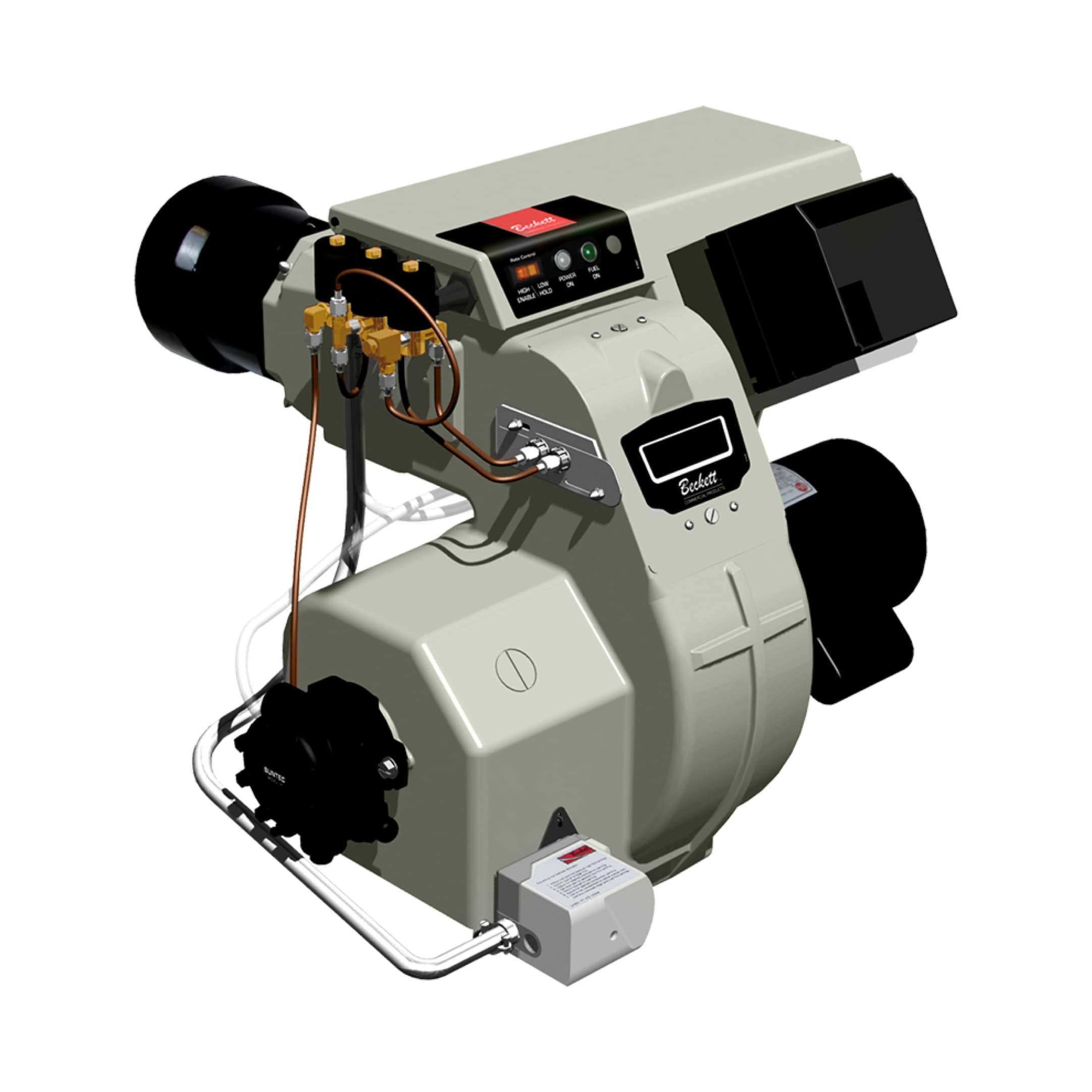
Understanding Burners & Combustion Valve Systems
Burners & Combustion equipment relies on solenoid valves as the critical control interface between fuel supply and ignition. These electromagnetic devices regulate gas flow with millisecond precision, directly impacting combustion efficiency, flame stability, and equipment lifespan. For maintenance teams, understanding valve operation separates reactive repairs from proactive system management.
Solenoid valves in combustion systems function as electronically controlled gates. When the control circuit energizes the coil, an internal plunger lifts, permitting fuel flow. Upon de-energization, spring tension closes the plunger, halting gas delivery. This binary action—fully open or fully closed—requires precise timing coordination with ignition sequences and flame detection circuits.
3G Electric has supported global industrial operations for over 35 years, distributing premium combustion control components that maintain this critical timing. The difference between a valve that opens in 100 milliseconds versus 150 milliseconds can determine whether your furnace achieves stable ignition or experiences delayed ignition with excess gas accumulation.
Valve Classification: Slow-Acting vs. Fast-Acting Response
Not all solenoid valves perform identically. Combustion systems require two distinct valve types, each serving specific operational phases:
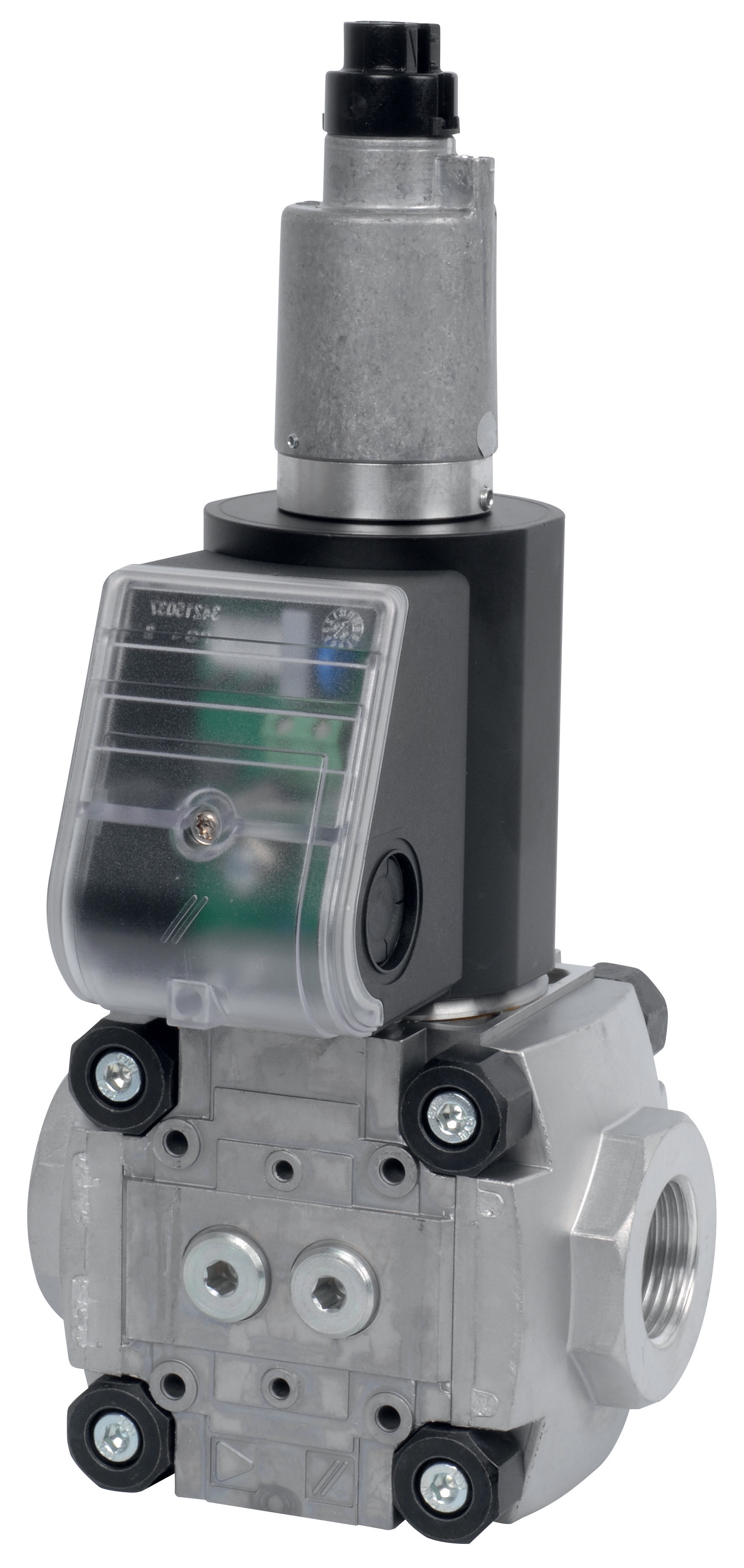
Slow-Acting (Slow Gas) Valves regulate fuel during main combustion phases when timing is less critical. These valves prioritize reliability and stable flow modulation. The CBM Slow Gas Solenoid Valve VAS 340R/LW handles high flow volumes (up to 340 cubic meters per hour) in large industrial furnaces, while the CBM Slow Gas Solenoid VAS 125R/LW serves medium-capacity systems requiring finer flow control. These valves typically open over 200-400 milliseconds, providing graduated pressure buildup that prevents pressure spikes and flame flare-ups.
Fast-Acting (Rapid Gas) Valves must respond within 50-100 milliseconds, critical for pilot light ignition and emergency shutoff sequences. The CBM Fast Gas Solenoid Valve VAS 110R/NW provides compact rapid response for smaller burner systems, while the CBM Fast Gas EV VAS 365R/NW delivers comparable speed in larger applications. These valves prioritize response time over gradual flow modulation.
Practical Implication for Maintenance: Mismatched valve types cause cascading problems. Installing a slow valve in a pilot circuit creates ignition delay and frequent pilot outages. Using a fast valve for main combustion invites violent flame ignition and pressure oscillations. During component replacement, always verify the original valve classification before sourcing alternatives.
Diagnostic Procedures: Identifying Valve Performance Degradation
Solenoid valve failures rarely announce themselves suddenly. Instead, performance degrades progressively, creating opportunities for predictive maintenance intervention.
Electrical Testing Protocol:
Before assuming mechanical failure, verify electrical continuity. Using a multimeter set to resistance mode, measure ohms across the solenoid coil terminals. Most combustion solenoids read between 20-100 ohms (specifications vary by model). Infinite resistance indicates open circuit failure—the coil has fractured internally. Zero or near-zero resistance suggests shorted windings. Both conditions require valve replacement.
Next, verify coil voltage supply during operation. The valve controller should supply rated voltage (typically 24V DC or 110V AC) when the flame safety relay energizes the valve circuit. Reduced voltage—perhaps 18V instead of 24V—indicates power supply degradation or undersized wiring. This creates sluggish valve opening, delayed fuel delivery, and erratic flame establishment.
Mechanical Response Testing:
With power disconnected, manually depress the solenoid plunger (the exposed stem on top of the valve body). It should move freely with moderate resistance from the internal spring. Stiff, grinding motion indicates internal corrosion or debris accumulation. Freely moving plungers suggest spring failure or internal seal deterioration.
For systems remaining operational, listen carefully during ignition cycles. A sharp, audible "click" indicates normal solenoid actuation. Dull thuds or absence of clicking suggests slow response or incomplete plunger travel. When combined with slow pilot ignition or intermittent flame establishment, this diagnostic points toward valve replacement.
Gas Flow Observation:
For accessible fuel lines, install pressure gauges before and after the solenoid valve. Normal pressure drop across an open valve should not exceed 0.2 bar. Excessive pressure differential (0.5+ bar) reveals partially blocked orifices from carbon buildup or internal membrane deterioration. This creates fuel starvation in the burner nozzle, reducing flame stability.
Maintenance teams often overlook this measurement, attributing poor combustion to nozzle problems when valve restriction is the actual culprit.
Integration with Control Relays: Timing Synchronization
Solenoid valves operate only when the flame safety relay energizes their circuits. The CBM Relay DMG 970-N MOD.03 serves as the intelligent coordinator, monitoring flame detection signals and controlling valve sequencing.
This relay receives input from the flame detector (UV or ionization sensor) and manages three critical outputs: pilot valve energization, main solenoid valve energization, and alarm signaling. The relay enforces precise timing—pilot valve opens first, waits 2-4 seconds for flame establishment, then opens the main valve. If no flame appears within this window, the relay de-energizes both valves and triggers a lockout condition.
Maintenance Impact of Relay Timing Drift:
As relay contacts age, their response times increase imperceptibly—perhaps 50 milliseconds per year. This gradual drift compounds with valve response delays. A system perfectly synchronized at installation may require 800 milliseconds for ignition after 5 years of operation. This extended delay permits excess gas accumulation, creating harsh flame ignition (visible as flame surges) and potential "puff" conditions that stress refractory linings.
Proactive maintenance includes measuring the complete ignition cycle time annually. Using a recording multimeter or oscilloscope across the flame detection output, calculate the interval between valve energization and flame signal receipt. Increasing trends warrant relay replacement before catastrophic puff events occur.
Preventive Maintenance Strategy: Extending Valve Service Life
Solenoid valves in burner systems experience thermal cycling stress that accelerates failure. Furnace startups elevate temperatures from ambient to 200°C+ within minutes. This thermal gradient flexes valve bodies and internal components, gradually fatiguing materials.
Fuel Quality Management: The most effective valve maintenance occurs upstream at the gas supply regulator. Ensure fuel supply includes coalescent filtration removing moisture and liquid carryover. Water droplets corrode solenoid internal surfaces, creating rough areas that impede plunger movement and reduce seal efficiency. High-quality filtration extends valve life by 40-60%.
Electrical Supply Stability: Verify that control power derives from regulated 24V or 110V supply, not directly from the main utility. Voltage fluctuations stress solenoid coils and reduce electromagnetic force. A regulated supply ensures consistent plunger acceleration, maintaining the critical timing margins your system was designed around.
Scheduled Inspection Intervals: For continuous-duty systems, implement quarterly valve inspection including resistance measurement and manual plunger testing. For seasonal equipment, inspect before each heating season. Replace valves demonstrating increased resistance (indicating coil degradation) or sluggish plunger movement before they fail during critical operation.
Replacement Procedure: When replacing a solenoid valve, always install a new sealing gasket and apply anti-seize compound to threaded connections. This prevents future seizure that complicates future maintenance. Verify the replacement valve matches the original in valve class (slow vs. fast), flow rating, and electrical specifications.
Conclusion
Burners & Combustion valve performance directly determines equipment reliability, efficiency, and safety. Maintenance teams armed with diagnostic procedures and understanding of valve classification can identify degradation before failures cascade through the combustion control system. 3G Electric's 35+ years supporting global industrial operations has demonstrated that preventive valve management—combined with quality component selection—reduces unplanned downtime and extends overall system lifespan significantly. Implement these diagnostic and maintenance strategies to establish predictable combustion performance across your facility.