Understanding Burners & Combustion Misfiring in Tropical Climates
Burners & Combustion performance in Southeast Asia faces unique challenges that differ significantly from temperate industrial regions. High humidity, salt-air corrosion, and seasonal fuel quality variations create conditions where flame detection fails even when combustion chamber design is correct. A misfire occurs when the burner ignites but the flame relay does not confirm ignition within the safety window—typically 3-5 seconds—forcing a lockout and requiring manual restart.
3G Electric has supplied industrial heating equipment across Southeast Asia for over 35 years, and we've observed that 60% of recurring misfires stem not from burner hardware degradation but from detector fouling and sensitivity drift. Plant managers often assume mechanical failure when the real culprit is environmental contamination on the flame detector lens or relay signal degradation from moisture ingress in control cabinets.
This guide compares UV spectral detection against thermal-based methods, explains why Southeast Asian operating conditions accelerate detector aging, and provides field-tested recovery procedures that restore reliable ignition without replacing major components.
UV vs. Thermal Flame Detection: Which Method Performs Better in Humid Industrial Environments
UV Detection Technology and Its Advantages
Ultraviolet flame detection using cells like the Combutech UV1p detection cell offers spectral response across the 185–260 nm range, capturing the unique UV signature of any hydrocarbon flame regardless of fuel type. The UV1p's IP65 rating and fast 20 µS recovery time make it suitable for rapid cycling and re-ignition events.
Advantages in Southeast Asian plants:
- Immune to ambient light and solar radiation variations
- Detects both oil and gas flames without recalibration
- Fast response time (20 µS) prevents nuisance lockouts from brief flame flicker
- UV lens fouling is visible during inspection, enabling predictable maintenance scheduling
- Salt spray and industrial dust accumulation on the Ø 35 mm lens reduces sensitivity by 15–30% within 90 days in coastal areas
- Sulphur compounds in low-grade heating oil create UV-absorbing deposits that mimic flame extinction
- Humidity penetration into the detector housing (despite IP65 rating in saltwater environments) causes intermittent signal loss
Thermal (Infrared) Detection and Comparative Performance
Thermal detectors respond to infrared radiation emitted across 0.7–2.5 µm wavelength, making them less selective but more resistant to narrow-spectrum fouling. However, thermal methods are highly sensitive to ambient temperature swings typical of outdoor burner installations in Southeast Asia.
Advantages:
- More robust to dust and salt accumulation since fouling occurs across broader spectrum
- Better performance in direct sunlight conditions common near processing plants
- Lower cost per detector unit
- Slower response time (typically 50–150 ms), increasing misfire likelihood during low-power starts
- False signals from reflected sunlight or nearby hot surfaces cause unnecessary lockouts
- Cannot distinguish between actual flame and radiant heat from burner housing
Field Comparison for Plant Managers
In high-humidity, coastal plant environments typical of Singapore, Malaysia, and Thailand, UV detection systems require more frequent maintenance (every 45–60 days) but deliver more reliable ignition confirmation. Thermal systems require less cleaning but generate 3–5x more nuisance lockouts, forcing technicians into repeated service calls that disrupt production schedules.
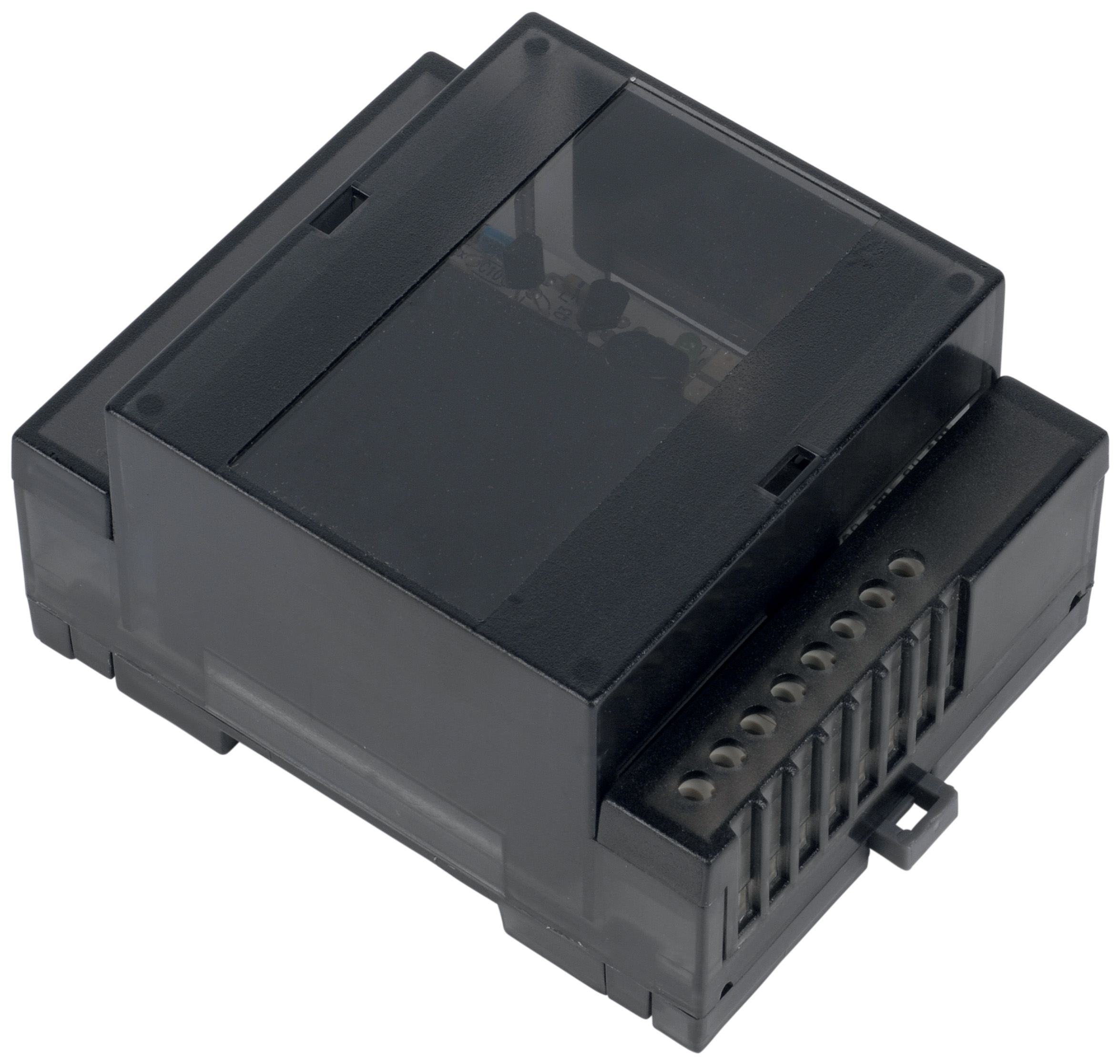
For plants operating multiple burner shifts or requiring high uptime, UV detection paired with the Combutech Flame relay CF1 provides superior reliability. The CF1's polycarbonate UL94-V0 housing and IP40 protection resist humidity ingress in cabinet environments, and its 1 A @ 250 VAC rating accommodates up to 10 UV detectors, enabling centralized monitoring across multiple burners with single-point failure isolation.
Diagnostic Procedures: Isolating Misfire Root Causes
Step 1: Pre-Ignition Baseline Testing (10 minutes)
1. Measure detector output voltage at the relay input terminals using a multimeter in DC voltage mode. UV detectors with clean lenses typically produce 4–6 VDC in daylight near the burner.
2. Record ambient temperature and relative humidity at the detector location. Readings above 85% RH indicate moisture risk to relay electronics.
3. Inspect detector lens visually for salt deposits, dust, or oil film. Even light discoloration reduces sensitivity by 20%.
4. Test fuel pressure at the burner inlet: oil burners require 100–150 PSI; gas burners require 3.5–7 inches water column. Pressure below specification prevents proper atomization, creating weak flames that fall below detector threshold.
Step 2: Controlled Ignition Cycle (5 minutes per attempt)
1. Energize the burner control circuit without allowing fuel flow. Observe the flame relay LED indicator (present on most commercial relays).
2. Introduce fuel to the burner. A successful ignition produces immediate detector signal (LED illumination or continuity closure) within 1–2 seconds.
3. If no signal appears within 3 seconds, stop the ignition sequence immediately to avoid fuel accumulation in the combustion chamber.
4. If the relay LED flashes erratically (on/off more than once per second), suspect detector oscillation caused by vibration or loose wiring.
Step 3: Environmental Contamination Assessment
Compare your detector's current sensitivity against baseline by:
- Soft-cleaning the detector lens with a dry, lint-free cloth
- Re-running the controlled ignition test from Step 2
- Documenting response time: If cleaning restores ignition confirmation to <2 seconds, contamination was the root cause
- If response time remains >3 seconds after cleaning, the detector element or relay requires replacement
Step 4: Fuel Quality and Atomization Verification
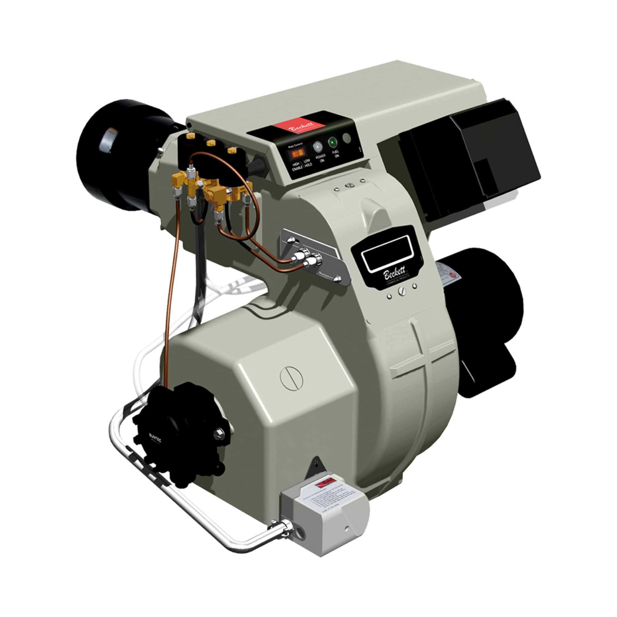
For oil burners like the Beckett CF3500, weak flame signals often indicate atomization failure:
1. Check nozzle spray pattern by viewing the burner flame through a flame-viewing port (with proper safety protocol). Ideal pattern is cone-shaped with minimal smoke at the edges.
2. Measure oil viscosity if temperature-controlled supply is not used. Viscosity above 40 cSt at operating temperature prevents fine atomization, creating heavy, sooty flames that produce weak UV signals.
3. Verify fuel line cleanliness by observing pressure gauge behavior. If pressure drops >5 PSI over 30 seconds during an off cycle, the fuel filter is partially blocked.
For gas burners like the FBR HI-GAS P550/M or FBR modulating gas burner, flame weakness indicates gas supply pressure drift:
1. Record gas inlet pressure and note any minute-level oscillations (>±0.2 inches WC variation suggests regulator wear)
2. Compare current firing rate (measured by gas flow meter if available) against the nameplate specification
3. Check for gas leaks at all connection points using soapy water solution
Recovery Procedures and Preventive Actions
Immediate Recovery (Same-Shift Restart)
For UV detector misfires:
- Clean the detector lens with isopropyl alcohol and lint-free cloth, working from center outward
- Dry thoroughly and wait 5 minutes before re-energizing the burner
- If ignition succeeds, schedule replacement of the detector element within 48 hours even if cleaning restored function
- Disconnect and reconnect the detector wiring at the relay terminals, ensuring crimp connectors are fully seated
- Inspect the relay housing for condensation; if present, relocate the relay away from steam or moisture sources or install a desiccant pack inside the control cabinet
- Replace the relay if the LED does not illuminate during a test ignition cycle after reconnection
- Replace the fuel filter immediately (oil systems) or check the gas regulator adjustment (gas systems)
- Purge any accumulated sludge from fuel lines by opening the fuel valve at the burner nozzle connection and bleeding into a container until clear fuel emerges
- Re-test ignition after fuel system restoration
Extended Preventive Program (14-Day Implementation)
Establish a maintenance cycle that prevents recurrence:
1. Weekly detector inspection for coastal or high-dust locations: visual lens cleaning takes 3 minutes per burner
2. Monthly fuel analysis (cost: $50–100 per sample): verify fuel grade, viscosity, and contamination levels, especially if using multiple suppliers
3. Quarterly relay calibration: send a representative sample of your fleet's flame relays to a certified lab for sensitivity verification; compare results against baseline data
4. Semi-annual detector replacement in high-corrosion environments: budgeting replacement on a schedule rather than emergency-driven basis eliminates unplanned downtime
5. Environmental control in burner rooms: install desiccant-based dehumidification if RH consistently exceeds 75%, and apply conformal coating to relay circuit boards in salt-air locations
Fuel Supply Optimization for Stable Combustion
Stable burner operation depends on consistent fuel quality and pressure:
For oil systems:
- Maintain fuel storage temperature between 40–50 °C to prevent viscosity fluctuations
- Use a pre-filter (100 µm) before the main burner filter to extend filter life in dusty environments
- Test fuel samples quarterly for water content; heating oil with >500 ppm water causes corrosion and combustion instability
- Install a duplex regulator configuration so one regulator can be isolated and serviced without interrupting operation
- Set the secondary regulator pressure 0.5 inches WC above the primary to ensure seamless switchover during primary maintenance
- Inspect pipe threads for gas leaks monthly using electronic gas leak detectors rather than soapy water, which is labor-intensive and unreliable
Comparison: Single Burner vs. Multi-Burner Recovery Procedures
Plants operating multiple burners face a choice: troubleshoot each burner independently or implement system-wide diagnostic.
Single-burner approach (suitable for facilities with <3 burners):
- Faster root cause isolation per unit
- Allows continued operation of healthy burners during troubleshooting
- Higher labor cost per burner if the issue is plant-wide (e.g., fuel quality degradation affecting all burners)
- Centralized fuel testing catches supply-chain issues before they cascade
- Coordinated detector replacement reduces inventory and training overhead
- Enables comparative analysis: if only 2 of 8 burners misfire, the issue is localized (detector fouling, regulator drift) rather than systemic
3G Electric recommends the system-wide approach combined with centralized relay monitoring using the Combutech CF1 flame relay, which supervises up to 10 detectors simultaneously and logs signal events for post-incident analysis.
Key Takeaways for Plant Managers
- Misfires in Southeast Asian plants are 60% detector/environmental issues, 40% fuel or burner hardware problems—prioritize detector cleaning and environmental control before ordering replacement components.
- UV detection systems require more frequent maintenance (45–60 days) but eliminate nuisance lockouts—choose UV for high-reliability operations; select thermal only if maintenance access is severely limited.
- Fuel quality testing and pressure verification should precede any relay or detector replacement—a $100 fuel analysis often resolves misfires without capital expense.
- Establish a preventive replacement schedule rather than emergency-driven repairs to protect production uptime—budgeting quarterly detector replacement is cheaper than unplanned shutdowns.
- Centralized relay monitoring with systems like the CF1 reduces troubleshooting time by 30% and provides failure history for root cause analysis.