Understanding Ignition Delay in Burners & Combustion Systems
Ignition delay—the time between initial spark and stable flame detection—is one of the most overlooked yet critical performance metrics in industrial burner operations. When ignition delay exceeds design specifications, you risk unburned fuel accumulation, combustion chamber pressure spikes, and safety system lockouts that disrupt production.
At 3G Electric, we've supported plant operations across Singapore and Southeast Asia for over 35 years. In that experience, we've found that ignition delay failures rarely indicate catastrophic equipment failure. Instead, they point to systematic maintenance gaps: electrode degradation, spark timing misalignment, fuel delivery inconsistency, or flame detection circuit drift. This guide walks you through the diagnostic sequence plant managers need to identify and resolve these issues before they escalate.
Ignition delay problems manifest in several ways: repeated burner lockouts on startup, delayed flame establishment (typically 3–5 seconds when design expects 1–2 seconds), partial ignition followed by cutoff, or successful ignition on second attempt only. Understanding which symptom you're experiencing narrows the diagnosis significantly.
Section 1: Pre-Ignition System Checks and Spark Quality Verification
Before investigating fuel delivery or flame detection, verify that the ignition system itself can deliver consistent, high-energy spark. Many ignition delays originate in the spark transformer output, electrode condition, or air gap.
Electrode Inspection and Gap Verification
Direct spark ignition systems depend on precise electrode spacing. Over 1,000+ operating hours, thermal cycling causes electrode erosion, creating irregular spark paths and weak ignition energy transfer.
- Shut down the burner and allow cooling to room temperature (minimum 30 minutes for oil burners, 15 minutes for gas burners)
- Remove electrode assemblies according to your burner's service manual; document original positioning with photographs
- Inspect electrode tips under magnification (10x minimum) for pitting, carbon buildup, or surface oxidation
- Clean electrodes with a soft brass brush; never use abrasive pads that create micro-fractures
- Measure electrode gap with a non-conductive gauge (spark plug gap tool, 0.025" precision minimum). Most industrial systems specify 0.080–0.125" gaps; verify your equipment manual
- Reinstall electrodes to exact original gap—misalignment by 0.015" can reduce spark effectiveness by 30–40%
A faulty spark transformer may show normal AC voltage at primary but insufficient high-voltage output.
- With the burner offline, measure primary voltage at the transformer input terminals using a multimeter set to VAC. Record the reading; it should match your control system design voltage (typically 120 VAC or 240 VAC)
- If primary voltage is low (±5% tolerance), investigate the control circuit and power supply before proceeding
- If primary voltage is correct, test secondary output using a high-voltage probe (non-contact type, rated 10 kV minimum). Safe secondary output typically shows 8–12 kV at the electrode gap during test fire
- If secondary output is absent or below 6 kV, the transformer requires replacement—do not attempt field repair
- Document all readings in your maintenance log; sudden voltage drops on repeat testing indicate transformer degradation
Even with excellent spark, ignition fails if the combustion mixture is outside the flammable range.
- For oil burners: verify fuel delivery pump pressure at the burner nozzle during initial spark phase (not during full flame). Correct pressure range is typically 80–120 PSI; low pressure (below 70 PSI) results in coarse droplets that ignite slowly
- For gas burners: confirm fuel gas pressure at the burner inlet during ignition is at least 2–3 inches of water column above atmospheric; low pressure causes lean mixture and delayed flame
- Test air supply to the combustion chamber using a handheld manometer at the air inlet; confirm the burner fan is delivering design airflow (specifications vary by model, but typically 500–2000 CFM for industrial systems)
- Verify no blockages in the air inlet screen or fan outlet
Section 2: Flame Detection Circuit and Relay Diagnostics
Once the burner ignites, the flame detection system must recognize stable flame within 1–3 seconds and signal the control relay to maintain fuel supply. Delayed flame detection—or failure to detect flame at all—causes the control system to interrupt fuel and trigger a safety lockout.
UV Flame Detection Cell Testing
The Combutech UV1p detection cell is a standard flame sensor in many Southeast Asian industrial installations. Its 185–260 nm spectral response captures UV radiation from the flame, but contamination, misalignment, or aging reduces sensitivity.
- Inspect the UV cell window (sapphire lens) for soot, oil spray, or condensation. Clean with a soft, lint-free cloth and isopropyl alcohol; never scrub or use abrasive cleaners
- Verify the cell is aimed directly at the flame (not at the burner housing or firebox wall). Misalignment by more than 15° reduces detection probability by 50%
- Test the UV cell output using an oscilloscope connected to the flame detection circuit (at the control module input). During steady flame, the signal should show a clean AC waveform at 50–100 Hz with amplitude of 0.5–2 VAC. Noise, intermittent signal dropout, or low amplitude indicates cell degradation or loose wiring
- If the UV cell output is weak but the cell appears clean, measure the cell resistance using an ohmmeter (burner off, cell disconnected). Typical resistance is 100 kΩ–1 MΩ depending on ambient light; very high resistance (>10 MΩ) suggests internal contamination or failure
- Document signal quality photos with an oscilloscope; this baseline helps detect drift on future startups
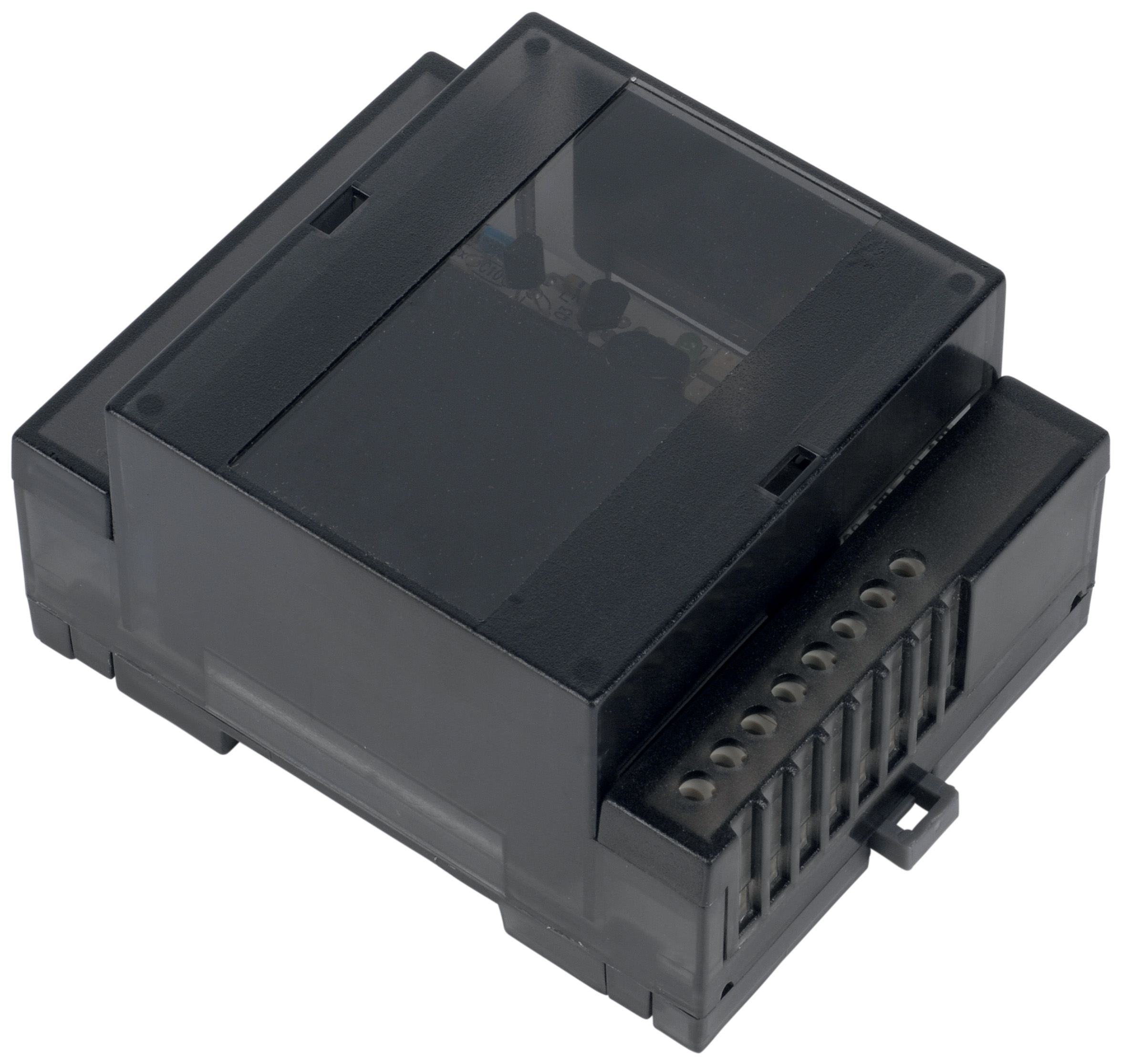
The Combutech Flame relay CF1 amplifies and filters UV cell signals, then triggers fuel supply continuation. If the relay is slow to respond or requires excessive UV signal strength, ignition delay increases.
- With the burner in test-fire mode (electrode sparked but fuel valve closed), measure the delay between first UV signal appearance and relay contact closure. Connect a multimeter (set to resistance or continuity) across the relay contacts; record the delay time using a stopwatch or video timer. Acceptable response is typically <500 milliseconds; delays exceeding 1 second indicate relay drift or UV threshold setting shift
- If relay response is slow, check the control module's flame sensitivity potentiometer (if adjustable on your model). A setting too conservative requires strong UV signal before relay closes; slight sensitivity reduction improves response. Consult your control module manual for adjustment procedure and safe range
- Verify relay contacts for pitting or corrosion. Open the relay housing (if accessible) and inspect contact surfaces; dark spots or white deposits indicate oxidation. Clean contacts gently with isopropyl alcohol on a cotton swab. If pitting is visible (tiny craters), contact replacement is recommended
- Test relay coil resistance using an ohmmeter (relay de-energized, disconnected): typical coil resistance is 500 Ω–2 kΩ. Open circuit (infinite resistance) indicates a failed coil; very low resistance (<100 Ω) suggests a shorted coil. Either condition requires relay replacement
Loose or corroded connections in the flame detection circuit create intermittent signal dropout, causing the control system to misinterpret brief flame loss as ignition failure.
- Visually inspect all connectors between the UV cell, flame relay, and control module for corrosion (green or white deposits), loose pins, or bent terminals
- Disconnect and reconnect all connectors three times, observing for any resistance or grinding sensation; smooth mating indicates good contact
- Measure resistance across each connector using an ohmmeter (connections de-energized): resistance should be <0.1 Ω. Higher readings indicate contact degradation and warrant pin cleaning or connector replacement
- In humid or salt-air environments (common in Singapore), apply dielectric grease to connector pins before reinstalling to prevent future corrosion
Section 3: Fuel Delivery Timing and Solenoid Valve Coordination
Ignition delay also depends on fuel delivery timing: the fuel solenoid must open at precisely the moment the spark begins, not before or after. Timing misalignment causes the burner to attempt ignition in the absence of fuel (dry fire) or with excess fuel (carryover from previous cycle).
Solenoid Valve Actuation Testing
- Locate the fuel solenoid valve in your burner assembly. Most industrial systems use a 120 VAC or 240 VAC coil
- With the burner in manual test-fire mode, listen for a distinct electrical "click" at the solenoid coil as fuel ignition begins. The click should be sharp and immediate (within 100 ms of ignition command); a delayed or absent click indicates a sluggish or failed solenoid
- Measure solenoid coil voltage during test fire using a multimeter set to VAC. Voltage should match the coil specification (typically 120 VAC ±10%). If voltage is low (below 110 VAC), investigate the control circuit power supply; if voltage is correct but the solenoid doesn't click, the coil is likely open (failed) and requires replacement
- Inspect the solenoid plunger for free movement. With the burner offline and solenoid de-energized, gently push on the plunger stem; it should retract smoothly and return under spring force. Stiff movement indicates internal corrosion or varnish buildup; soak the solenoid in penetrating oil for 1–2 hours and repeat the test. If movement doesn't improve, solenoid replacement is necessary
- Install a pressure gauge at the fuel inlet to the burner (before any pressure regulators). Record steady-state fuel pressure during normal operation (e.g., 100 PSI for oil systems, 3–5 PSI for gas systems, depending on your equipment)
- During a manual test-fire cycle, observe whether fuel pressure rises smoothly and reaches setpoint within 1 second of ignition command. If pressure rises slowly or overshoots and then corrects, the fuel pump or pressure regulator may require adjustment or replacement
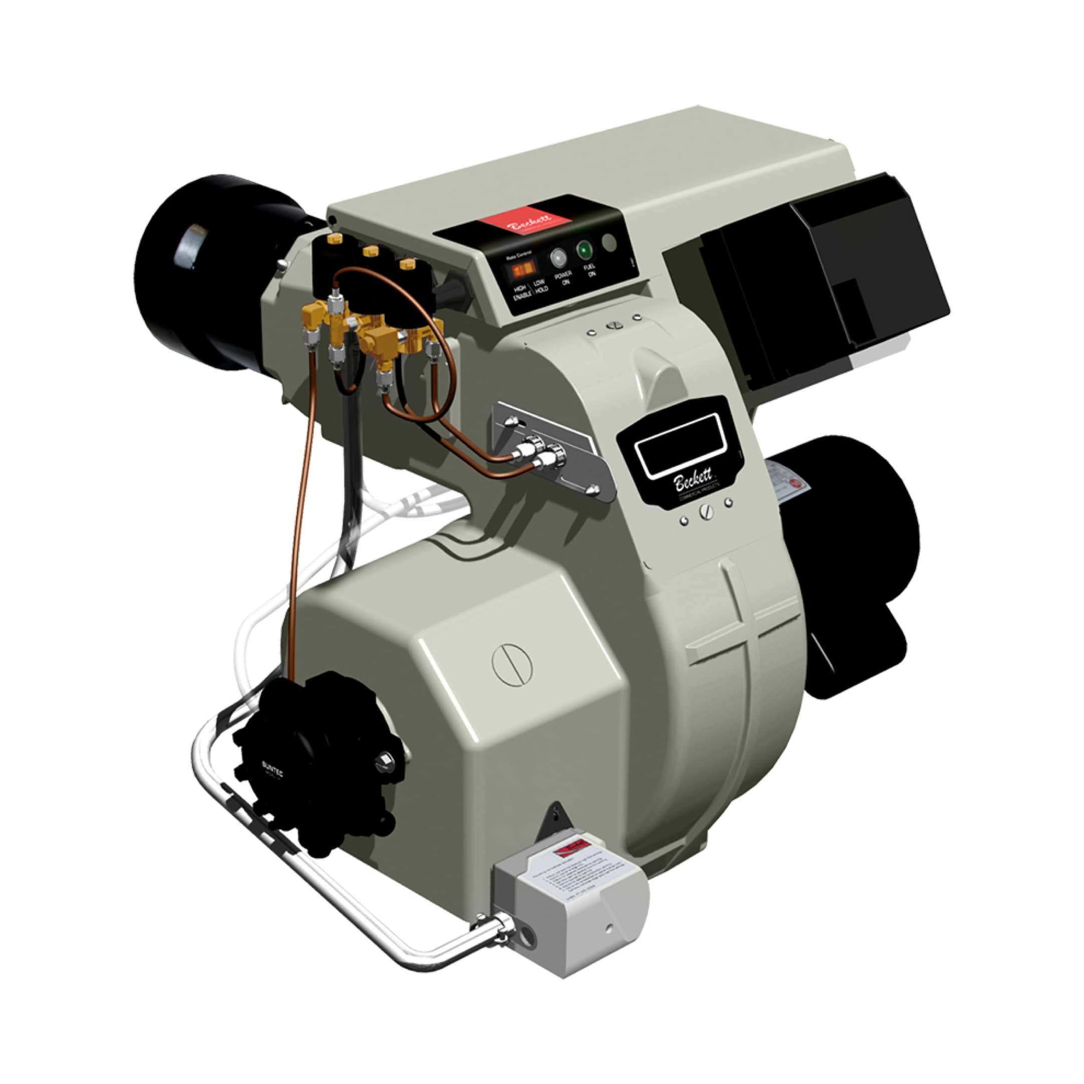
- For oil burner systems using the Beckett CF3500 oil burner, verify that the fuel pump delivery rate (17–35 GPH on this model) matches your system design. If ignition delay is excessive with no electrode or flame detection issues, low fuel flow (e.g., 15 GPH actual vs. 25 GPH designed) means the combustion mixture is too lean. Check the fuel filter for blockage and the pump displacement setting per the burner manual
Many industrial control modules allow adjustment of ignition dwell time (duration spark is energized before fuel solenoid opens) and fuel cutoff delay (time between flame loss detection and solenoid shutoff). Incorrect settings extend ignition delay.
- Consult your control module datasheet for dwell time and cutoff delay settings. Typical dwell time is 0.5–2 seconds; typical cutoff delay is 0.5–1 second
- If ignition delay is excessive, try increasing dwell time by 0.5 seconds (consult your service manual for safe adjustment range to avoid over-pressurization). Test-fire the burner and record new ignition delay
- Reduce dwell time only if you observe repeated dry-fire events (spark without fuel); shorter dwell ensures fuel solenoid opens earlier in the spark sequence
- Document all timing adjustments in your maintenance log with before/after ignition delay times; this history helps detect drift over months or years
Section 4: Integrated Diagnostics and Corrective Action Planning
Ignition delay failures often involve multiple factors: e.g., slightly worn electrodes + low flame detection sensitivity + aging spark transformer = 3–5 second delay. Addressing one issue in isolation may not resolve the symptom.
Systematic Diagnostic Sequence
1. Baseline measurement: Record actual ignition delay using a stopwatch or data logger during a cold start (burner offline for >2 hours). Repeat three times; average the results.
2. Electrode and spark testing: Clean electrodes, verify gap, test transformer output. Re-measure ignition delay. If delay improves by >0.5 seconds, document the change and schedule electrode replacement every 1,000 operating hours going forward.
3. Flame detection testing: Clean UV cell, test signal quality, verify relay response time. If relay response is slow, adjust sensitivity potentiometer (+10% adjustment, test-fire, re-measure delay). Document final sensitivity setting.
4. Fuel delivery testing: Verify solenoid actuation timing, fuel pressure rise rate, and pump flow rate. If fuel pressure is low, clean the fuel filter and re-test; if pressure remains low, the pump requires service.
5. Final integration test: Run five consecutive burner ignition cycles (cold starts, 30-minute intervals between cycles). Measure ignition delay on each cycle and calculate mean and standard deviation. If mean delay exceeds design specification by >20%, or if standard deviation (variation between cycles) exceeds 0.5 seconds, implement one additional corrective action: e.g., replace the spark transformer or UV cell.
Preventive Maintenance Schedule
Based on 35 years of field experience, 3G Electric recommends:
- Monthly: Visual inspection of electrodes and UV cell window for soot or corrosion; clean as needed
- Quarterly: Measure electrode gap and reset if drift exceeds 0.010"; test flame relay response time and document
- Annually: Replace spark transformer and UV cell if ignition delay is increasing (trending toward specification limit); replace solenoid valve coil if voltage drop exceeds 5% from nameplate
- On every lockout: Perform full diagnostic sequence (sections 1–3 above) before returning burner to service
| Symptom | Most Likely Cause | Quick Fix |
|---------|------------------|----------|
| Ignition delay 3+ seconds, then stable flame | Weak spark or low flame detection sensitivity | Clean electrodes and UV cell; adjust sensitivity +5–10% |
| Intermittent ignition (succeeds every 2–3 attempts) | Loose wiring or corroded connector | Disconnect and reconnect all flame circuit connectors; clean pins with isopropyl alcohol |
| Ignition delay varies 1–4 seconds (unstable) | Degraded spark transformer or UV cell aging | Test transformer output and UV cell resistance; replace if out of spec |
| Ignition succeeds but flame loss occurs within 10 seconds | Fuel pressure too low or flame detection threshold too high | Increase fuel pressure +5 PSI; reduce flame relay sensitivity by 5% |
| Solenoid clicks late (audible delay before fuel flows) | Solenoid coil degraded or voltage sag | Test solenoid voltage during ignition; if <110 VAC, investigate power supply; if voltage correct, replace solenoid |
When to Escalate to Equipment Replacement
If after completing sections 1–4 your ignition delay remains >20% above design specification, or if the diagnostic process reveals multiple component failures (e.g., weak spark transformer + slow relay + low fuel pressure), budget for targeted equipment replacement:
- For oil burner systems, the Beckett CF3500 offers proven ignition performance (direct spark, 17–35 GPH) and is widely supported in Singapore; consider replacement if existing unit exceeds 10 years in service
- For large-scale gas heating, the FBR HI-GAS P550/M delivers modulating combustion (2325–6395 kW output) with integrated flame monitoring, reducing ignition delay risk through advanced control architecture
- Flame detection components like the Combutech Flame relay CF1 and Combutech UV1p detection cell are cost-effective replacements that collectively improve system reliability when multiple older sensors are in use
Work with your equipment supplier (3G Electric can provide support across Singapore and Southeast Asia) to specify compatible replacement components that match your burner type and control system voltage.
Summary: Ignition Delay Troubleshooting for Plant Managers
Ignition delay failures reflect systematic degradation in electrode, spark, flame detection, or fuel delivery systems. By following the four-section diagnostic sequence—spark quality → flame detection → fuel timing → integrated testing—plant managers can isolate root causes and prioritize corrective actions without guesswork.
Key takeaway: ignition delay is rarely a single-component failure. Instead, it typically involves 2–3 marginal systems (e.g., moderately worn electrodes + aging UV cell + slow relay response) that individually pass inspection but collectively exceed design performance limits. Addressing the lowest-performing component first (often spark quality) typically recovers 50–70% of lost performance; additional gains require flame detection and fuel delivery tuning.
Document all measurements, adjustments, and maintenance actions in your burner log. Over time, this data reveals aging trends—e.g., electrode gap drifting 0.005" per 500 hours, UV cell sensitivity declining 5% per year—enabling predictive replacement scheduling and preventing unplanned shutdowns.