Introduction to Burners & Combustion Ignition Diagnostics
When a burner refuses to light or exhibits intermittent flame detection, the problem often traces back to ignition timing or spark gap issues rather than fuel delivery failures. Burners & Combustion systems depend on precise timing synchronization between electrode spark generation and fuel injection—a window typically measured in milliseconds.
With over 35 years of experience distributing industrial heating equipment, 3G Electric has supported thousands of HVAC contractors through ignition-related troubleshooting. The critical insight: most ignition failures stem from five controllable factors—spark gap distance, electrode degradation, timing relay malfunction, control module signal delay, and high-tension wire degradation.
This guide provides field-tested diagnostic procedures you can execute with basic tools and multimeters, helping you resolve ignition problems on-site and minimize customer downtime.
Section 1: Understanding Spark Gap Geometry and Measurement
The Spark Gap Window
The spark gap—the distance between the two electrodes where electrical arc occurs—is the foundation of reliable ignition. Unlike traditional automotive spark plugs, industrial burner electrodes operate at much higher voltages (typically 8,000–10,000 volts) and require tighter tolerance control.
Correct gap settings vary by burner model:
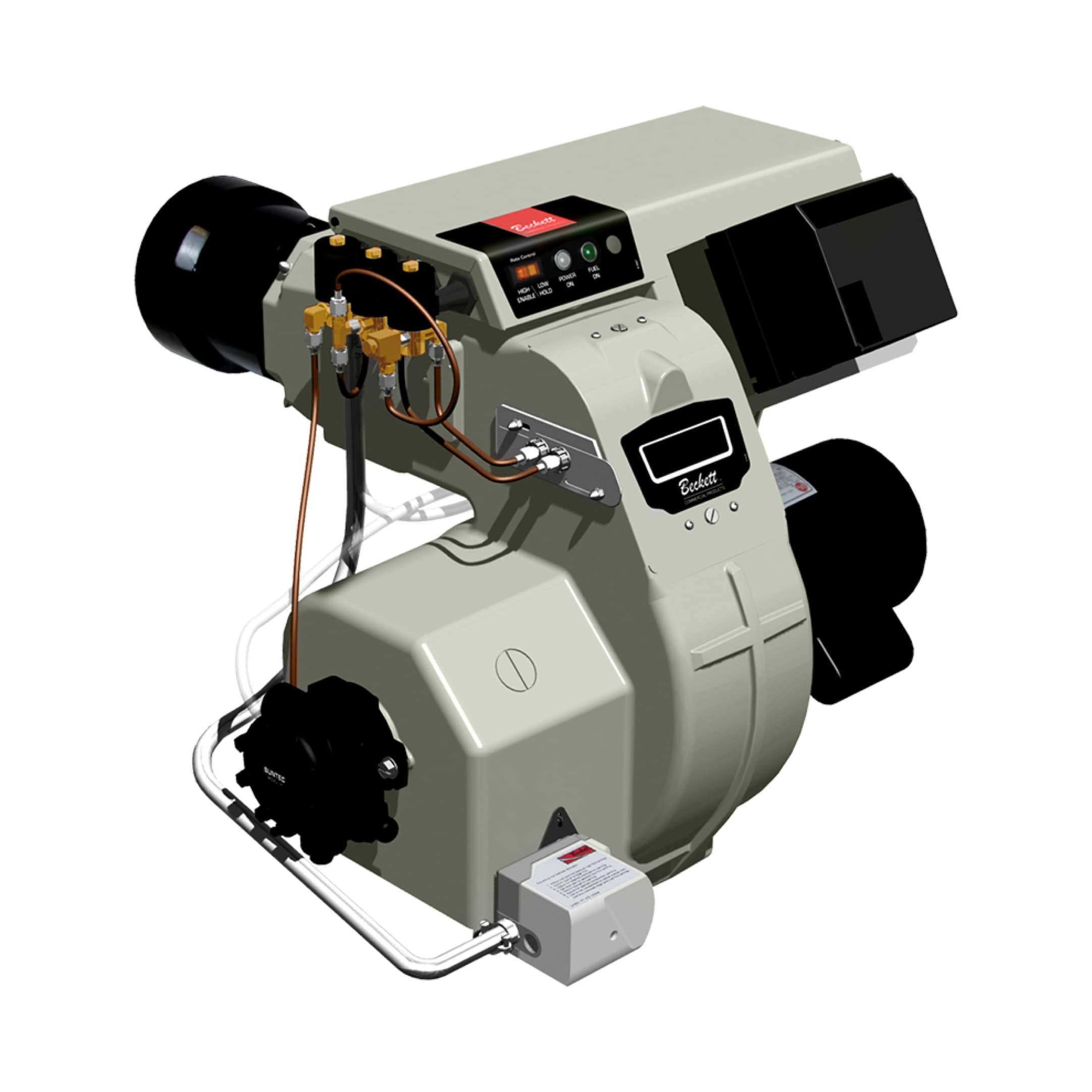
- Oil burners (like the Beckett CF3500 Oil Burner): 0.095–0.110 inches (2.4–2.8 mm)
- Direct-spark gas burners: 0.125–0.150 inches (3.2–3.8 mm)
- Electrode-to-burner body clearance: Minimum 0.5 inches on all sides
Gap degradation occurs progressively. Even 0.010 inches of erosion can reduce spark energy by 20–30%, leading to weak flame detection and delayed ignition.
Field Measurement Procedure
Tools needed:
- Wire feeler gauge set (0.001-inch increments)
- Spark plug socket (for electrode removal on accessible designs)
- Notebook for baseline documentation
Step 2: Locate the spark electrode assembly. On most units, it mounts on the burner front or inside the combustion chamber.
Step 3: Using the feeler gauge, insert the appropriate wire perpendicular to both electrode surfaces simultaneously. You should feel light contact—not loose, not tight.
Step 4: Record the measurement and compare to the burner specification plate or installation manual. Document any deviation greater than ±0.005 inches.
Step 5: Visually inspect electrode tips for:
- Pitting or crater formation (indicates erosion)
- White oxide coating (suggests moisture or contamination)
- Asymmetrical wear (sign of mechanical vibration during spark)
If gap measures outside specification or electrodes show visible erosion, electrode replacement is required—not adjustment.
Section 2: Diagnosing Ignition Timing and Control Signal Issues
The Ignition Sequence Timeline
Sucessful combustion requires precise orchestration:
1. t=0 ms: Burner control module energizes (receives start command)
2. t=50–100 ms: High-tension transformer energizes, primary coil current flows
3. t=100–150 ms: Secondary coil voltage reaches spark gap electrode
4. t=150 ms onward: Continuous spark (repeated pulses at 50–120 Hz depending on design)
5. t=200–300 ms: Fuel solenoid opens, atomizer spray reaches combustion zone
6. t=300–500 ms: Flame front develops, UV detector senses ionization
7. t=500+ ms: Flame relay (such as the Combutech Flame relay CF1) confirms stable combustion
If ignition timing drifts beyond this window, the spark may extinguish before fuel reaches the ignition zone, or the fuel may arrive before robust spark energy develops.
Multimeter Diagnostics for Control Circuits
Primary Circuit Testing (Low Voltage):
Your multimeter's DC voltage function is your primary diagnostic tool here.
Step 1: Set the multimeter to 20 VDC range. Connect the red probe to the burner control module's transformer input terminal. Connect the black probe to ground (burner chassis).
Step 2: Trigger the burner start sequence (push ignition button or enable via control system).
Step 3: Observe voltage during ignition phase (first 2–3 seconds):
- Normal: 24 VDC (±2V) steady, or 110/240 VAC (±10V) depending on control voltage
- Low voltage (<20 VDC): Indicates inadequate power supply, loose connections, or upstream control board failure
- Zero voltage: Control signal never reached module; suspect control relay or switch malfunction
- Voltage spikes (rapid fluctuation): Suggests electromagnetic interference or damaged transformer primary coil
Secondary Circuit Testing (High Voltage):
High-voltage testing requires caution. Do not touch electrode leads or spark plug wires during operation.
Step 1: Use a non-contact spark tester (available at automotive supply stores, $15–30). Hold the tester 2–3 inches from the spark electrode while the ignition circuit is energized.
Step 2: A healthy transformer produces visible blue/white spark inside the tester window.
Step 3: If no spark appears:
- Confirm primary voltage is present (step above)
- Check high-tension wires for visible cracks or degradation
- Verify electrode gap meets specification
- Consider transformer failure (open secondary coil) requiring replacement
Timing Relay Diagnostics
Older burner systems use mechanical or electromechanical timing relays to sequence spark, fuel solenoid, and blower activation. Modern systems use solid-state control modules.
If your system uses a mechanical timing relay:
Step 1: Locate the relay on the control panel (usually a cylindrical or rectangular component labeled "Timing Relay" or "Sequence Timer").
Step 2: With power off, listen for mechanical "click" sounds when you manually toggle the burner start switch. Absence of clicking indicates relay failure.
Step 3: With power on and during ignition startup, use your multimeter to measure voltage across the relay coil. You should see the specified coil voltage (typically 24 VAC or 24 VDC) for 2–5 seconds during ignition phase, then de-energize.
Step 4: If voltage remains continuous or never appears, suspect a stuck relay contact or failed coil winding.
If your system uses a solid-state electronic module:
Step 1: Locate the control module (small circuit board with indicator LEDs for spark, fuel, and flame status).
Step 2: Observe LED behavior during startup:
- Spark LED: Should illuminate for first 2–4 seconds
- Fuel LED: Should illuminate 0.2–0.5 seconds after spark LED
- Flame LED: Should illuminate 0.5–1.0 seconds after fuel LED
- Loose DIP switch settings (if module is configurable)
- Damaged capacitors or transistors on the module board
- Module replacement if diagnostic mode shows persistent sequencing errors
Section 3: High-Tension Wire and Connector Integrity
Physical Inspection Protocol
High-tension (HT) wires that carry 8,000+ volts from the transformer to the spark electrodes degrade over time due to UV exposure, thermal cycling, and ozone production from the spark itself.
Step 1: With power OFF, visually inspect the entire length of HT wires from transformer secondary to electrode:
- Look for cracks in insulation (even hairline fractures)
- Check for discolored or brittle sections (typically tan or brown instead of original black)
- Confirm wires are not touching metal chassis, which would ground the spark
- Verify boots (connectors at each end) are fully seated and not corroded
Step 3: Use a multimeter set to Ohm (resistance) mode:
- Set to 20 MΩ (megohm) range
- Disconnect the HT wire from both ends
- Probe the wire center conductor at one end, then at the other
- Healthy wire: 5–15 MΩ resistance (varies by length and gauge)
- Degraded wire: >50 MΩ or open circuit (∞ ohms) indicates internal fracture
If resistance is abnormally high or infinite, the wire must be replaced.
Step 4: Test insulation breakdown by setting your multimeter to the highest Ohm range available (typically 200 MΩ):
- Place one probe on the wire's outer insulation
- Place the other probe on the center conductor at the opposite end
- Healthy wire: ∞ ohms (insulation prevents current flow)
- Compromised wire: <1 MΩ indicates moisture infiltration or insulation failure
Replacement is mandatory if insulation resistance drops below 1 MΩ.
Connector and Boot Replacement
Connectors at the transformer and electrode ends degrade independently of the wire itself. Corrosion inside connectors introduces resistance, reducing spark voltage at the gap.
Step 1: Disconnect the HT wire from the transformer secondary.
Step 2: Inspect the female connector (on the transformer side) for:
- Green or white oxidation (corrosion)
- Loose or bent contact pins
- Cracks in the plastic boot
- Electrical contact cleaner (not WD-40 or general-purpose lubricant)
- Fine wire brush or pencil eraser for light oxidation
- Replacement connector if oxidation is heavy or contact deformation is visible
Step 5: Repeat for the electrode-end connector.
Section 4: Integration with Flame Detection Systems
Spark-to-Flame Detection Timing
Ignition timing is only half the equation. The UV detector that confirms flame presence must receive signal within a specific window after spark initiation.
The Combutech UV1p detection cell features a 20-microsecond recovery time at 10% duty cycle, enabling rapid flame confirmation. However, if spark timing is delayed beyond the burner's fuel injection window, the UV detector never sees flame despite the spark firing correctly.
Common scenario: Spark fires at t=150 ms, but fuel doesn't reach the combustion zone until t=400 ms due to slow solenoid response. The flame appears too late—after spark has ceased. The UV detector sees nothing, and the control module initiates shutdown and retry sequence.
Diagnostic procedure:
Step 1: During normal operation, use a digital oscilloscope (if available) to simultaneously measure:
- Voltage at the high-tension electrode (tells you when spark is active)
- Output signal from the UV detector (tells you when flame is detected)
- Slow spark development (gap too large, weak transformer)
- Delayed fuel injection (solenoid sticking, supply pressure low)
- Weak flame development (poor atomization, low fuel flow)
- Many modern modules flash specific LED patterns to indicate ignition delay or flame detection failure
- Consult the module's manual for LED code interpretation
- Patterns showing "spark OK, flame fail" point to fuel delivery, not ignition
- Patterns showing "no spark" or "spark weak" point back to Section 2 diagnostics
Flame Relay Confirmation
Once the UV detector confirms flame, the Combutech Flame relay CF1—rated 1 A @ 250 VAC and supporting up to 10 UV detectors—latches the burner into running mode, bypassing the ignition circuit.
If ignition timing is correct but the flame relay fails to engage:
Step 1: Confirm UV detector is receiving unobstructed view of the combustion zone (no soot, no debris on lens).
Step 2: Test UV detector output using a multimeter on DC voltage mode:
- Probe the detector's output line
- During flame, output should jump from 0 V to 4–8 VDC (varies by detector model)
- If output stays at 0 V despite visible flame, detector failure is likely
- Measure voltage across the relay input terminals during normal flame operation
- Should show 24 VDC (or 120 VAC) ±2V
- If voltage is present but relay doesn't energize, coil is open and relay requires replacement
Practical Troubleshooting Workflow
When a burner shows ignition or startup problems, execute this sequence:
1. Confirm Power & Safety (2 minutes)
- Verify main power is present at the control panel
- Ensure burner is in safe shutdown state (flame should be off)
- Confirm fuel supply is available (check pressure gauge if equipped)
- Measure electrode gap using feeler gauge
- Compare to specification plate
- If gap exceeds spec by >0.005 inches, replace electrodes
- Measure primary circuit voltage during ignition startup
- If zero or abnormally low, suspect control relay or power supply failure
- If normal, proceed to Step 4
- Use non-contact spark tester near the electrode
- If spark is visible and robust, proceed to Step 5
- If spark is weak or absent, test high-tension wire resistance (5 minutes) and replace wire or connector if out of spec
- Observe the burner control module's fuel LED behavior during startup
- If fuel LED activates more than 1 second after spark LED, suspect solenoid response issue (beyond ignition scope)
- If timing looks correct, proceed to Step 6
- Observe flame LED on control module
- If flame LED activates within 1–2 seconds of fuel injection, ignition and flame detection are working
- If flame LED never activates despite visible flame in the combustion chamber, test UV detector output and flame relay (see Section 4)
This workflow isolates the failure to ignition timing, spark generation, control sequencing, or flame detection—enabling you to order the correct replacement part and minimize return visits.
Maintenance Intervals to Prevent Ignition Failures
Based on 35+ years of field experience, 3G Electric recommends:
- Spark electrode inspection: Every 12 months or 2,000 operating hours
- High-tension wire resistance testing: Every 24 months
- Electrode replacement: Every 3–4 years (industrial duty) or when gap wear exceeds 0.005 inches
- Timing relay or control module inspection: Every 5 years or after unplanned shutdowns
- Complete ignition system overhaul: Every 7–10 years for 24/7 operation systems
Proactive inspection during annual maintenance prevents most ignition-related emergency calls.