Understanding Burners & Combustion Valve Architecture
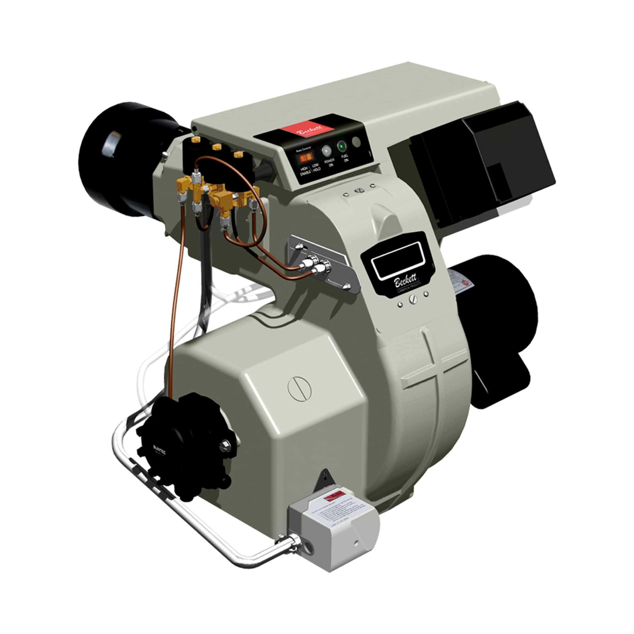
Burners & Combustion control relies on a coordinated ecosystem of components working in millisecond-precise intervals. For procurement engineers, understanding valve architecture is fundamental to specifying the right equipment and avoiding costly integration failures. The core principle is straightforward: gas flow must be controlled at multiple points—initial supply (slow valves for modulation), rapid shutoff (fast valves for safety), and relay-mediated sequencing.
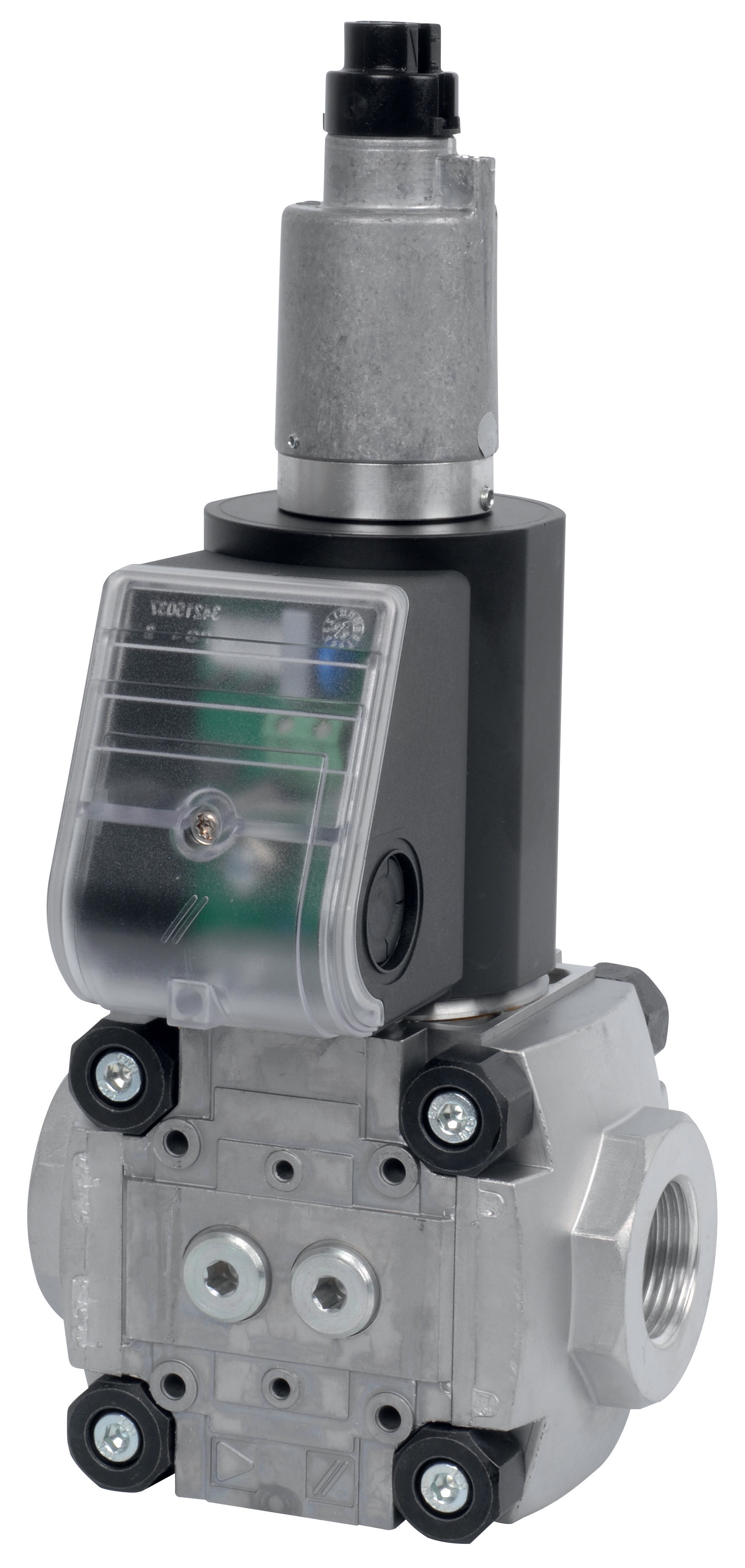
The gas solenoid valve sits at the heart of this architecture. Unlike manual ball valves, solenoid valves respond to electrical signals, enabling automated combustion sequences. In Burners & Combustion systems, you'll typically encounter two functional categories: slow gas valves for proportional fuel regulation and fast gas valves for emergency shutoff. The CBM slow gas solenoid valve VAS 340R/LW represents a robust solution for larger capacity burners requiring modulated flow control, while the VAS 125R/LW handles medium-capacity applications. For rapid response shutoff scenarios, the VAS 110R/NW and VAS 365R/NW provide the millisecond response times critical to safety shutdown sequences.
With 35+ years of experience as an global industrial equipment distributor, 3G Electric has guided hundreds of procurement teams through valve selection complexities. The difference between correct and incorrect valve specification often determines whether your Burners & Combustion system operates smoothly for years or requires emergency intervention within months.
Practical Valve Selection Criteria for Procurement Engineers
Selecting valves for Burners & Combustion systems requires evaluating five core parameters: pressure rating, flow capacity (Cv value), response time, electrical specifications, and integration compatibility.
Pressure Rating: Industrial burners typically operate between 0.5 to 6 bar gas pressure. Your valve must be rated for your system's maximum operating pressure plus a safety margin. Undersized pressure ratings lead to valve failure under peak demand; oversized ratings create cost overruns without performance benefit. When procuring, verify that your valve's pressure classification matches burner specifications from the OEM documentation.
Flow Capacity (Cv): This dimensionless number indicates how much gas the valve passes at specified pressure drop. Higher Cv values accommodate larger burners. The VAS 340R/LW slow valve provides higher Cv than the VAS 125R/LW, making it suitable for burners exceeding 500 kW. Procuring a valve with insufficient Cv will throttle your burner's power output; excessive Cv reduces valve precision during modulation phases.
Response Time: This is the interval between electrical signal and valve movement. Fast gas valves must respond within 200-500 milliseconds for safety compliance. Slow valves allow 800-1500ms, suitable for steady-state modulation. The VAS 110R/NW fast valve and VAS 365R/NW meet international safety standards requiring rapid fuel shutoff. When procuring safety-critical systems, always verify response time certifications.
Electrical Specifications: Solenoid coils require specific voltage (24V DC, 110V AC, 230V AC) and power consumption (typically 2-5W). Your burner control system must supply matching voltage. Mismatched voltage specifications are among the most common procurement errors, resulting in valves that don't respond to control signals.
Integration Compatibility: Your valve must physically and functionally integrate with existing control relays and flame detection systems. The CBM Relay DMG 970-N MOD.03 represents a common control interface that coordinates multiple valves in Burners & Combustion sequences. When procuring valve sets, ensure all components are compatible with your burner's relay configuration.
Integration Strategy: Building Coordinated Burners & Combustion Systems
Successful Burners & Combustion procurement moves beyond individual component selection to system-level integration planning. Most failures occur at the interfaces between valves, relays, and burner controllers—not from valve defects themselves.
A typical industrial burner sequence involves: purge phase (air circulation without fuel), ignition phase (pilot fuel + ignition spark), main fuel ramp-up (slow valve modulation), steady-state operation (continuous flow monitoring), and safety shutdown (fast valve closure). Each phase requires precise valve signaling.
The DMG 970-N MOD.03 relay orchestrates this sequence by receiving flame-detection feedback and sending electrical commands to slow and fast solenoid valves. During procurement specification, document this sequence in writing. Include timing intervals, pressure setpoints, and valve response expectations. This documentation becomes invaluable when troubleshooting integration problems post-installation.
For global operations, consider regional pressure standards and electrical codes. North American burners may specify different pressure classes than European or Asian equipment. 3G Electric's 35 years serving international customers reveals that valve specification errors frequently stem from overlooking these regional variations. When procuring for multi-regional deployments, specify valves separately for each region rather than attempting single-SKU standardization across incompatible systems.
Coordinate your valve procurement timeline with burner delivery. Valves are often lead-items; delays in valve availability cascade into project delays. Establish contingency valve lists during procurement planning, identifying approved alternative SKUs acceptable to your burner OEM.
Specification Documentation and Procurement Best Practices
Procurement engineers should develop standardized Burners & Combustion component specifications preventing recurring errors across multiple installations.
Create a Component Matrix: Document for each burner type: required slow valve model(s), fast valve model(s), relay specifications, electrical requirements, and pressure ratings. Include installation drawings showing valve locations and connection points. This matrix becomes your procurement standard, reducing decision-making time on repeat projects.
Establish Supplier Relationships: Reliable valve suppliers understand Burners & Combustion integration nuances beyond basic product specifications. 3G Electric's quarter-century-plus experience includes troubleshooting integration issues that generic industrial suppliers cannot address. Develop relationships with suppliers offering technical consultation during specification phases, not just transactional sales.
Verify Certifications: Solenoid valves for Burners & Combustion must comply with EN 676 (gas burner safety), UL 797 (gas valve specifications), or equivalent regional standards. During procurement, request certification documentation proving your valves meet applicable standards. Non-certified valves may cost 30% less but expose your operation to liability and regulatory non-compliance.
Plan for Redundancy and Spares: Mission-critical burner systems warrant dual solenoid valve configurations where one valve serves as active control and the other as backup. Simultaneously procure spare valves for emergency replacement. A failed solenoid in production environment may warrant immediate replacement rather than waiting for standard lead times.
Document Integration Diagrams: Work with your controls integrator to generate electrical schematics showing valve connections to the relay control system. Include terminal assignments, voltage drops, and signal timing. This diagram prevents cross-wiring errors during commissioning—perhaps the most common field installation mistake.
Test Protocol Specification: Include in procurement orders a requirement for factory testing confirming valve responsiveness, pressure ratings, and relay signal compatibility. Request test certificates validating each valve batch rather than assuming compliance.
Procurement engineers recognizing Burners & Combustion valve selection as strategic rather than transactional achieve superior system reliability. The 5-10% procurement cost premium for properly specified, certified, and documented valve systems returns dividends through reduced downtime, extended equipment life, and operational safety.