Understanding Burners & Combustion System Architecture
Burners & Combustion equipment form the thermal heart of industrial operations, requiring comprehensive understanding of system architecture and integration points. A modern burner system consists of multiple interdependent components working in precise coordination: the primary burner unit handling fuel atomization and ignition, control electronics managing modulation and safety sequencing, flame detection apparatus monitoring combustion quality, and fuel delivery systems ensuring consistent pressure and metering.
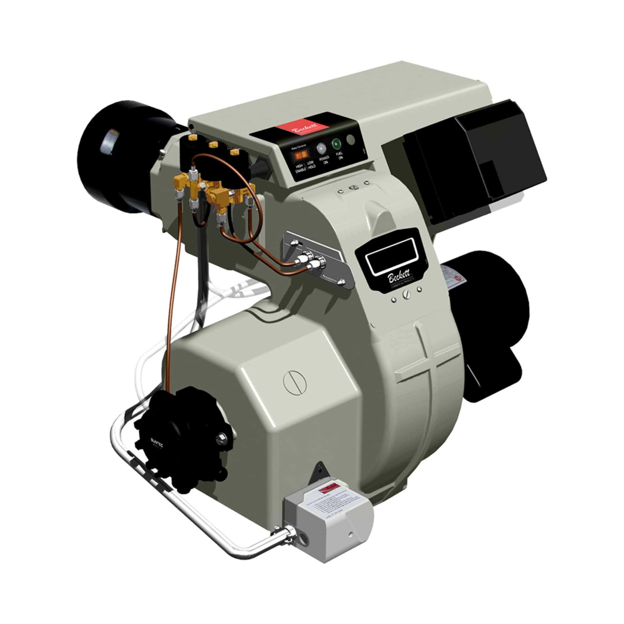
With over 35 years of experience distributing industrial equipment globally, 3G Electric has supported thousands of maintenance teams in managing complex burner installations across diverse industries. The FBR BURNER GAS X5/MF TL EL VC LPG FBR Gas X5 Modulating Burner represents the modern standard for gas combustion applications, featuring die-cast aluminum construction with high-pressure fan technology enabling precise modulation control when equipped with optional PID modulation kits and temperature probes.
Understanding burner combustion principles begins with recognizing three critical requirements: adequate fuel supply at correct pressure, proper air-fuel mixing ratios, and reliable ignition and flame monitoring. Each element contributes to combustion efficiency, emissions compliance, and operational safety. Maintenance teams must develop working knowledge of how burner design parameters—including nozzle selection, air shutter positioning, and fuel injection methods—directly influence flame characteristics, heat output stability, and diagnostic indicators.
Preventive Maintenance Protocols for Burner Reliability
Preventive maintenance represents the most cost-effective strategy for ensuring burner reliability and preventing catastrophic failures. Industrial burners operate under extreme thermal and mechanical stress, making systematic inspection and component replacement essential for maintaining consistent performance and safety compliance.
Critical Maintenance Intervals and Inspection Points
Establish quarterly inspection schedules examining the following components: combustion chamber cleanliness and refractory condition, fuel nozzle spray patterns and electrode positioning, air inlet screens and damper mechanism response, and burner control box electrical connections and component integrity. Monthly visual inspections should verify flame color (blue for clean gas combustion, indicating proper stoichiometry), absence of flame flickering or rollout conditions, and normal modulation response during load changes.
Fuel delivery system maintenance requires attention to pressure regulator calibration, fuel filter condition, and solenoid valve operation. The CBM VCS 1E25R/25R05NNWL3/PPPP/PPPP double solenoid valve CBM Double Solenoid Valve VCS 1E25R provides primary and secondary fuel shutoff functionality with integrated diagnostic capabilities. Schedule annual solenoid valve testing using multimeter continuity checks and pressure gauge verification at both pilot and main fuel circuits. Document pressure readings under operating conditions, establishing baseline values for trend analysis indicating developing valve degradation.
Replace air filters and combustion chamber inspection ports annually or more frequently in dusty environments. Degraded air filtration increases combustion instability, promotes carbon buildup, and reduces burner efficiency by 2-5% per month of operation. Inspect fan blade clearances and bearing lubrication status during preventive maintenance visits, as worn bearings increase vibration, accelerate component wear, and indicate impending bearing failure requiring urgent attention.
Seasonal Preparation and Shutdown Procedures
Before peak heating seasons, conduct comprehensive burner testing including pilot ignition reliability verification, main flame establishment within specified time parameters (typically 3-5 seconds), and response testing under minimum and maximum firing rate conditions. Test emergency shutdown procedures, confirming fuel cutoff within 1-2 seconds and proper burner purging before reignition cycles.
When shutting down burner systems for extended periods, purge all fuel lines with inert nitrogen gas, depressurize fuel circuits, and isolate electrical power supplies. Document final operating parameters including firing rate, combustion temperature, and any observed anomalies. Cover burner air inlet openings to prevent moisture and foreign debris accumulation during dormant periods.
Combustion Diagnostics and Troubleshooting Methodology
Systematic diagnostic approaches enable maintenance teams to identify combustion problems quickly, minimize downtime, and prevent repeat failures. Combustion issues manifest through multiple observable indicators that, when properly interpreted, guide efficient root cause analysis and component replacement decisions.
Flame Monitoring and Detection System Diagnostics
Flame detection systems represent critical safety components requiring regular diagnostic verification. The CBM Flame relay CF1 CBM Flame Relay CF1 monitors flame presence through ultraviolet or infrared detection, initiating safety shutdown sequences when flames extinguish unexpectedly. Test flame detection circuits monthly by observing relay response during burner startup and shutdown cycles. Verify that relays activate within 500 milliseconds of flame establishment and deactivate within 1 second following flame loss.
Common flame detection failures include: UV/IR cell contamination from combustion products (requiring gentle cleaning with soft brush and optical-grade solvent), sensor window fogging or discoloration (necessitating cell replacement), and compromised sensor mounting causing misalignment relative to flame envelope. Diagnostic procedure involves isolating the detector circuit, applying test voltage to relay inputs, and confirming relay coil energization and contact switching. If relay fails to respond, replace the sensor element rather than attempting repair, as detector responsiveness degrades progressively with contamination.
Control System Diagnostics and Component Testing
Control system failures frequently originate in safety relays, timer circuits, and solenoid driver stages rather than the burner itself. The CBM Relay CM391.2 30.5 1.2 CBM Relay CM391.2 30.5 1.2 functions as a master control module coordinating pilot ignition sequences, fuel valve energization timing, and flame monitoring integration. This module requires diagnostic testing using multimeter voltage measurements at control terminals and visual inspection of internal relay contacts for arcing damage or corrosion.
Develop a troubleshooting flowchart specific to your burner system:
Burner fails to ignite: Verify pilot fuel pressure at gauge ports (typically 3-5 bar), test pilot solenoid valve coil resistance (expected 200-1500 ohms depending on design), confirm spark ignition voltage at electrodes (minimum 12-15 kV), and inspect electrode gap (typically 3-5mm) for carbon bridging. If solenoid tests fail, replace the valve unit; never attempt internal valve repair as seal integrity cannot be verified after disassembly.
Flame extinguishes during operation: Check main fuel solenoid valve operation by listening for distinct audible click when energized, measure fuel pressure stability under firing conditions (pressure fluctuations exceeding ±0.5 bar indicate regulator problems), inspect fuel nozzle for carbon blockage by removing and examining spray pattern (should produce fine conical mist), and test flame detector circuit response by momentarily blocking flame with paper—the burner should shut down within 2-3 seconds.
Erratic modulation or hunting: Verify modulation motor response to control signal changes by observing smooth gradual movement without hesitation, measure feedback sensor output voltage across modulation range (should vary linearly without dead spots), inspect air damper linkage for mechanical binding or loose connections, and examine burner head for partial blockage that disrupts air-fuel mixing at reduced firing rates.
Excessive combustion noise or vibration: Inspect burner mounting bolts for looseness (torque to manufacturer specifications), examine fuel line routing for contact points against structure (should have isolation supports every 600mm), verify combustion chamber sealing integrity (loose refractory causes vibration transmission), and test fuel pressure regulator performance under varying fuel demand (pressure creep indicates worn regulator requiring replacement).
Pressure and Performance Measurement Techniques
Establish baseline pressure measurements for your specific burner installation: pilot fuel pressure at ignition solenoid inlet (typically 2-3.5 bar), main fuel pressure at burner entrance (typically 10-25 bar depending on nozzle rating), air pressure at forced draft fan outlet (typically 50-150 Pa water column), and flue gas oxygen content at stack (typically 2-4% for natural gas combustion indicating optimal air-fuel ratio).
Use digital manometers with ±0.5% accuracy for all pressure measurements, recording values in spreadsheet format to establish trend data. Pressure trends revealing gradual increases indicate component degradation: rising pilot pressure suggests fuel regulator wear, increasing main fuel pressure indicates feed system component failure, and rising fan outlet pressure suggests air path blockage. Monthly trend analysis enables predictive maintenance scheduling before component failure causes unexpected downtime.
Advanced System Integration and Component Coordination
Modern burner systems integrate multiple control components requiring coordinated operation and proper electrical sequencing. The CBM Base LGK AGM17 CBM Base LGK AGM17 provides integration mounting and terminal coordination for multi-component control systems, enabling simplified troubleshooting and modular component replacement.
Electrical Integration and Safety Sequencing
Burner control systems implement standardized safety sequences protecting equipment and personnel from hazardous operating conditions. Typical sequence includes: power-on system check (confirms flame detector response and safety relay integrity), lockout/purge cycle (energizes burner fan for 30-60 seconds without fuel to eliminate combustible atmosphere), pilot ignition and flame establishment (igniter active for 8-10 seconds while monitoring flame detection), main fuel solenoid energization (after pilot flame confirmed and flame detector signal stable), and continuous flame monitoring with automatic shutdown if flame extinguishes.
Maintenance teams should document exact control sequences for installed systems, testing sequence operation monthly through control panel diagnostic cycles. Verify lockout cycle duration matches system design (incorrect purge times allow unburned fuel accumulation), confirm flame detection delay matches specified parameters (prevents nuisance shutdowns from startup noise interference), and test safety relay overload protection ensuring thermal shutdown occurs within 3-5 minutes of solenoid current overload.
Modulation System Performance and Fine-Tuning
Optional modulation kits convert burner systems to proportional firing control, enabling precise output matching to load demand and improving efficiency 8-15% compared to on-off control. Modulation systems use temperature feedback sensors and closed-loop proportional-integral-derivative (PID) control algorithms continuously adjusting fuel and air supply to maintain setpoint temperature within ±2-3°C accuracy.
When commissioning modulation systems, establish PID tuning parameters specific to load mass and system thermal response characteristics. Typical initial settings use proportional band 50-150°C (range over which burner modulates from 0-100%), integral time 300-900 seconds (determines how quickly system corrects steady-state error), and derivative time 10-60 seconds (provides predictive response anticipating load changes). Under-damped systems oscillate around setpoint (proportional band too narrow, derivative time too high), while over-damped systems respond sluggishly (proportional band too wide, integral time too long). Fine-tune settings during off-peak operation, documenting final parameters in equipment logbook for reference during future troubleshooting.
The FBR BURNER GAS X5/MF TL EL VC LPG FBR Gas X5 Modulating Burner achieves stable modulation across 5:1 or higher turndown ratios when properly integrated with precision fuel metering and air control components. Monthly verification testing should confirm stable operation at 25%, 50%, 75%, and 100% load conditions, with temperature response settling within ±3°C of setpoint within 2-3 minutes of load change.
Temperature Monitoring and Thermal Safety Integration
Integrate flue gas temperature sensors and thermal switches protecting against critical fault conditions: high flue gas temperature (exceeding 250-280°C indicates blockage or inadequate air supply), uncontrolled heating (thermal runaway), and burner overfire conditions. Stack-mounted thermocouples provide continuous temperature feedback for control systems, while separate backup thermal switches provide hardwired shutdown protection independent of control electronics.
When installing temperature sensors, position thermocouples in representative flue gas flow locations (center of duct avoiding wall radiant effects), use compression fittings with thermowell protection against moisture and vibration, and verify thermocouple resistance (typically 5-15 ohms per 100 feet of extension cable). Test thermal switch operation quarterly by applying external heat source to switch housing until threshold temperature triggers switching action—confirm switch contacts open reliably without sticking or hesitation.
Maintenance Documentation and Performance Trending
Systematic documentation enables early detection of developing problems through performance trending and supports compliance with equipment warranties and regulatory requirements. Establish maintenance logbooks or digital tracking systems recording: equipment operating hours, dates and results of preventive maintenance activities, component replacement history with part numbers and supplier information, pressure measurements at standardized points, fuel consumption trends (gallons or cubic meters per operating hour), and any observed anomalies or emergency repairs performed.
Monthly fuel consumption analysis reveals combustion efficiency trends—increasing fuel consumption at constant load indicates developing efficiency loss from air path blockage, combustion chamber degradation, or fuel atomization problems. Quarterly pressure trend analysis reveals component wear before catastrophic failure: gradual pressure increases at constant load indicate regulator wear, while sudden pressure drops suggest component failure or leak development.
With 35 years of global industrial equipment distribution experience, 3G Electric recommends organizing maintenance activities into three tiers: (1) daily operational checks (flame color and burner response), (2) monthly diagnostics (pressure measurements, relay testing, flame detector verification), and (3) quarterly comprehensive inspections (component tear-down, seal replacement, electrical resistance verification). This structured approach, supported by comprehensive documentation, ensures consistent performance, minimizes unplanned downtime, and extends equipment service life 20-30% beyond minimum design specifications.