Understanding Your Burners & Combustion System: The Foundation for Reliability
Industrial burners & combustion systems are the backbone of countless manufacturing and heating operations worldwide. When these systems fail, production halts and costs escalate rapidly. Drawing on 3G Electric's 35+ years of experience distributing industrial equipment across global markets, this troubleshooting guide focuses on practical prevention and rapid diagnosis strategies that plant managers can implement immediately.
Burners & combustion systems operate across three critical phases: fuel preparation, ignition, and flame maintenance. Understanding how these phases interact is essential for identifying problems before they become emergencies. A modern industrial burner integrates mechanical, electrical, and fluid dynamics components working in millisecond-precise coordination. When performance degrades, the root cause often lies in inadequate maintenance protocols rather than component failure.
Section 1: Establishing a Preventive Maintenance Schedule for Burners & Combustion
Daily Visual Inspections
Your first line of defense against burner failure is daily visual inspection. Assign a trained operator to check:
- Flame appearance: Color should be blue with minimal yellow. Yellow flames indicate incomplete combustion or contaminated fuel.
- Burner sound: Normal operation produces steady combustion noise. Intermittent firing or popping sounds suggest ignition timing issues.
- Fuel pressure readings: Record baseline pressures. Gradual increases indicate filter fouling; sudden drops suggest leaks or supply problems.
- Visible fuel leaks: Check around burner nozzles, valve connections, and fuel line joints.
- Control panel indicators: Verify all status lights function correctly and no fault codes appear.
Document these observations in a maintenance log. Trends over two weeks reveal developing problems—a 5% monthly pressure increase, for example, warns of imminent filter replacement needs.
Weekly Deep Inspections
Every seven days, dedicate 30 minutes to comprehensive inspection:
- Electrode condition: Remove the burner head (when safely cooled) and inspect ignition electrodes for carbon buildup. Clean with soft wire brushes; damaged electrodes require replacement before they cause no-start conditions.
- Nozzle examination: Oil burners accumulate residue at atomizer tips. Use approved nozzle cleaning tools to remove deposits without damaging the precise spray pattern. Never use compressed air—metal shavings contaminate fuel lines.
- Fuel filter pressure drop: Most filters display condition via color indicators. Replace when indicator shows "change." Don't wait for pressure symptoms to appear.
- Airflow verification: Feel airflow at inspection ports. Reduced airflow indicates fan blade fouling or blocked air intake dampers.
- Valve operation: Manually cycle solenoid valves when burner is off. All valves should click decisively. Sluggish response indicates carbon accumulation or seal degradation.
Monthly Comprehensive Maintenance
Once monthly, perform these critical procedures:
Combustion Analysis: Using a combustion analyzer (oxygen and CO measurements), verify:
- Oxygen levels: 2-4% for oil burners, 3-5% for gas burners
- CO levels: Below 200 ppm for healthy combustion
- Stack temperature: Record baseline—increases indicate fouling
- Water content: Any water present requires tank drainage and fuel polishing
- Particulate contamination: Visible sediment requires fuel system flushing
- Fuel viscosity: Seasonal viscosity changes affect atomization quality
Section 2: Rapid Diagnostic Procedures for Common Burners & Combustion Failures
No-Start or Delayed-Start Scenarios
When burners fail to ignite, follow this logical progression:
Step 1 - Safety Verification (First 30 seconds)
- Confirm electrical power to burner controller
- Verify fuel supply valve is open and tank isn't empty
- Check for active fault codes on control display
- Ensure thermostat call for heat is active
- Locate fuel pressure gauge (required on every burner)
- For oil burners: pressure should read 8-12 bar at rest, 13-15 bar during firing attempt
- For gas burners: pressure typically 10-25 mbar depending on burner rating
- If pressure is zero: Check fuel valve solenoid. Using a fast-response gas solenoid valve or a slow-response gas valve depending on your system design, listen for audible clicks during startup sequence. No click = electrical power issue; audible click but no pressure = internal valve failure requiring replacement
- Listen at the burner head during startup. You should hear a "click-click-click" of spark ignition (for direct spark systems) or observe a glowing ignition element (for hot-surface ignition)
- No spark or glow: Measure voltage at ignition transformer primary and secondary windings with a multimeter. If secondary voltage reads zero despite primary power present, the transformer has failed
- Spark present but no fuel: Fuel solenoid is faulty; isolate the valve for replacement. Using a slow-response solenoid valve in applications requiring precise fuel metering ensures dependable fuel cutoff and prevents hard starts
- Most modern burners include flame sensors (ultraviolet or infrared detection)
- Request the burner attempt one more startup cycle while you observe the flame
- If flame ignites but burner immediately shuts down (lockout occurs), the flame sensor isn't detecting combustion
- Clean the sensor lens—accumulated carbon blocks signal transmission. Use soft cloth with approved solvent; avoid scratching the sensor window
- If lockout persists after cleaning, the sensor or its amplifier requires replacement
Low Power Output and Efficiency Degradation
When burners operate but produce insufficient heat:
Combustion Quality Analysis:
- Measure oxygen content in flue gas. If oxygen reads above 5% for oil or 6% for gas, the air-to-fuel ratio is too lean
- Check fuel pressure. Oil burners below 12 bar or gas burners below the rated minimum produce incomplete atomization and weak flames
- Inspect nozzles for wear. Worn nozzles produce larger droplets or irregular spray patterns, reducing combustion efficiency by 5-15%
- Blocked air intakes reduce combustion oxygen availability
- Inspect inlet grilles and dampers for debris
- Measure fan motor amperage. Current above nameplate specification indicates fan blade fouling requiring cleaning
- Test fan bearing play—excessive play creates radial imbalance, reducing airflow volume
- Pressure drop across fuel filters should not exceed 0.3 bar at operating flow
- Clogged filters reduce pressure, forcing the burner controller to compensate, which increases electrical demand on pump motors
- Fuel line restrictions accumulate gradually. Inspect all feed lines for external damage and internal restrictions using pressure testing
Nuisance Shutdowns and Hunting Behavior
Burners that cycle on and off rapidly or shut down unexpectedly often suffer from control system issues:
Flame Stability Problems:
- Inspect nozzle condition first. Carbonized or damaged nozzles produce unstable flames that flicker, triggering false flame-loss signals
- Verify burner air intake is not pulsating. Restricted inlets create pressure fluctuations that extinguish marginal flames
- Check electrode gaps (for spark ignition): 2-3mm gaps are standard. Larger gaps require higher ignition voltage; smaller gaps may cause continuous re-ignition attempts
- Many industrial controllers include adjustable flame detection sensitivity. Verify sensitivity settings match commissioning values
- Electromagnetic interference from nearby motors or power lines can cause false flame-loss detection. Inspect control wiring shielding and bonding
- Test flame sensor responsiveness using controller diagnostic menus (available on most modern units). Sensor response time should be less than 2 seconds
- Pressure oscillations cause hunting. Install pressure gauges on fuel inlet and outlet lines
- Tank-mounted burners often experience supply pressure variation as tank level drops. Install a fuel pump to maintain constant pressure independent of tank level
- Air in fuel lines (common with suction-lift installations) causes pressure spikes and flame instability. Bleed air through fuel filter vents before each startup
Section 3: Strategic Component Selection for Burners & Combustion System Reliability
Equipment selection directly impacts maintenance frequency and system reliability. 3G Electric's 35+ years of industrial equipment experience demonstrates that matching component specifications to application requirements prevents cascading failures.
Fuel Valve Selection for Your Application
Solenoid valve performance significantly affects burner response time and fuel control precision:
- Fast-response valves like the CBM Fast gas EV VAS 365R/NW suit high-modulation burners requiring sub-second fuel delivery adjustments. These valves demand premium fuel filtration—use 10-micron filters minimum to prevent coil stiction
- Slow-response valves like the CBM Slow gas solenoid valve VAS 340R/LW excel in simple on-off burner applications. Their forgiving response characteristics tolerate minor fuel quality variations better than fast-response designs
- Dual-stage solenoids combine fast and slow valve characteristics, providing rapid startup while maintaining stable modulation. These suit applications transitioning between minimum and maximum fire
Matching valve response to your burner controller's firing pulse frequency prevents control instability. Controllers firing at 10 Hz require fast-response valves; lower-frequency controllers (2-5 Hz) tolerate slower valves.
Oil Burner Component Specifications
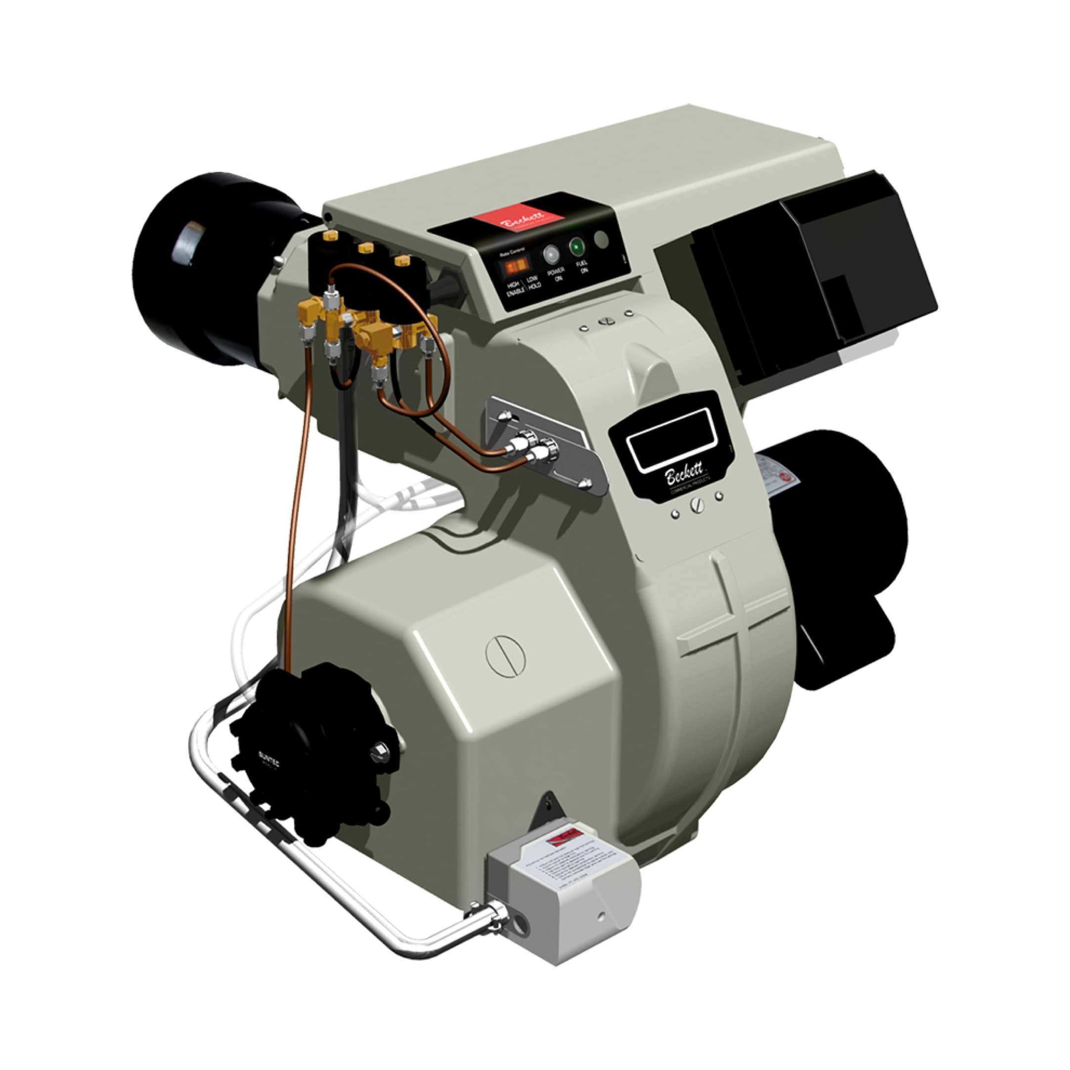
The Beckett CF3500 Oil Burner (17-35 GPH) represents industrial-grade oil combustion technology. When selecting or troubleshooting oil burners:
- Nozzle rating: Matched to your specific capacity requirement. A 35 GPH burner operating at 25 GPH (part load) produces poor atomization. Multi-burner installations or modulating systems solve this mismatch
- Pump pressure: Should maintain 13-15 bar during operation, controlled by pressure regulator. Regulators require annual cleaning to prevent hunting
- Fuel temperature: Viscosity varies with temperature. Winter operation in cold climates requires fuel heaters to prevent nozzle blockage
Section 4: Emergency Response and Minimizing Downtime
When critical burners fail during production, systematic troubleshooting saves hours of diagnostic time:
Immediate Response Protocol
1. Establish safe conditions: Shut down fuel supply at tank shutoff valve. Allow burner to cool. Verify no gas or oil escapes from nozzle area
2. Document baseline conditions: Photograph fuel pressure gauge readings, control panel display codes, and flame appearance if visible
3. Activate redundant systems: If backup burners exist, start them now while diagnosing the failed unit
4. Call technical support: Contact your equipment distributor (3G Electric maintains 24/7 support lines) with baseline data and fault codes. This accelerates remote diagnostics
15-Minute Diagnostic Decision Tree
Is fuel reaching the burner?
- Yes → Proceed to ignition system checks
- No → Replace fuel valve (solenoid); most failures are electrical, not mechanical
- Spark/glow present → Flame detection failure; clean or replace sensor
- No spark/glow → Ignition transformer failure; order replacement immediately
- Yes → Control system failure; requires controller diagnostics
- No → Nozzle fouling or air delivery problem; clean nozzle and verify airflow
Parts Inventory Recommendations
Maintain emergency stock of high-failure components:
- Two replacement nozzles (correct size for your burner)
- One complete fuel solenoid valve (verify fast/slow response type matches your system)
- Ignition electrode set
- Fuel filter cartridges (one full cartridge minimum)
- Control system fuses and relays
- Flame sensor (if your burner model uses replaceable sensors)
Storing spare components at the plant reduces emergency vendor response dependency and maintains production during component procurement delays.
Conclusion: Building Long-Term Burners & Combustion Reliability
Industrial burners & combustion system reliability depends on systematic preventive maintenance, rapid diagnostic capability, and strategic component selection. Plants implementing these practices report 40-60% reduction in emergency shutdowns and 20-30% improvement in fuel efficiency.
Your plant manager responsibilities include establishing maintenance discipline, training operators in daily observation, and maintaining technical documentation of performance trends. When failures occur, systematic troubleshooting procedures isolate root causes quickly, minimizing production loss.
3G Electric's 35+ years of global equipment distribution provide access to OEM-approved components, technical support, and maintenance training. Contact our team to schedule burner system assessment or discuss component upgrades matching your facility's operational requirements.

