Burners & Combustion: Diagnosing and Resolving Ignition Failures
Ignition system failures represent one of the most disruptive failure modes in industrial Burners & Combustion applications across Southeast Asia. When a burner fails to ignite or loses flame unexpectedly, production halts, safety systems lock out the equipment, and diagnostic time compounds the financial impact. Over 3G Electric's 35+ years serving the industrial equipment market throughout Southeast Asia, we've observed that 60–70% of ignition-related downtime stems from three addressable causes: contaminated or failed flame detection sensors, degraded pressure switch calibration, and inadequate air supply during the ignition phase.
Unlike control relay failures (which present obvious electrical symptoms) or nozzle blockages (which show gradual performance decline), ignition system faults often manifest as intermittent or complete loss of flame detection, leaving operators confused about whether the ignition attempt itself succeeded. This guide provides maintenance teams with structured diagnostic workflows, sensor testing procedures, and component specification guidance to resolve these issues systematically.
Section 1: Understanding Ignition System Architecture and Failure Modes
The Critical Role of Flame Detection in Burner Safety
Modern industrial burners rely on flame detection sensors to confirm ignition success within 1–3 seconds of the ignition command. The flame detector continuously monitors combustion and signals the control system to maintain burner operation or trigger a lockout if flame is lost. In Burners & Combustion systems, the flame detector serves as the primary safety interlock—if the signal degrades, the entire system fails safe by shutting down.
The Siemens Cell QRB4A-B036B40B flame detector commonly deployed in Southeast Asian industrial heating applications uses UV/infrared sensing to detect flame presence. These detectors are mounted directly in the burner combustion chamber, exposing them to extreme thermal cycling, soot accumulation, and thermal shock during ignition transients.
Common Ignition Failure Scenarios
Scenario 1: False Flame Loss After Successful Ignition — The burner ignites and sustains flame for 5–30 seconds, then unexpectedly shuts down. This typically indicates sensor contamination or a weakening UV/IR signal path. Root causes include: soot buildup on the detector lens, burner tube internal corrosion reducing light transmission, or misaligned detector optics after vibration.
Scenario 2: Immediate Ignition Lockout (No Flame Signal) — The ignition command fires, but the control system detects no flame within the allowed window (usually 1–3 seconds). This suggests: insufficient combustion air during ignition phase, spark plug or ignition transformer failure, fuel delivery delay, or complete flame detector failure.
Scenario 3: Intermittent Ignition Success — The burner requires multiple restart attempts before achieving stable flame. This points to marginal sensor signal strength, weak ignition spark, or insufficient fuel atomization at startup.
Pressure Switch Integration in Ignition Logic
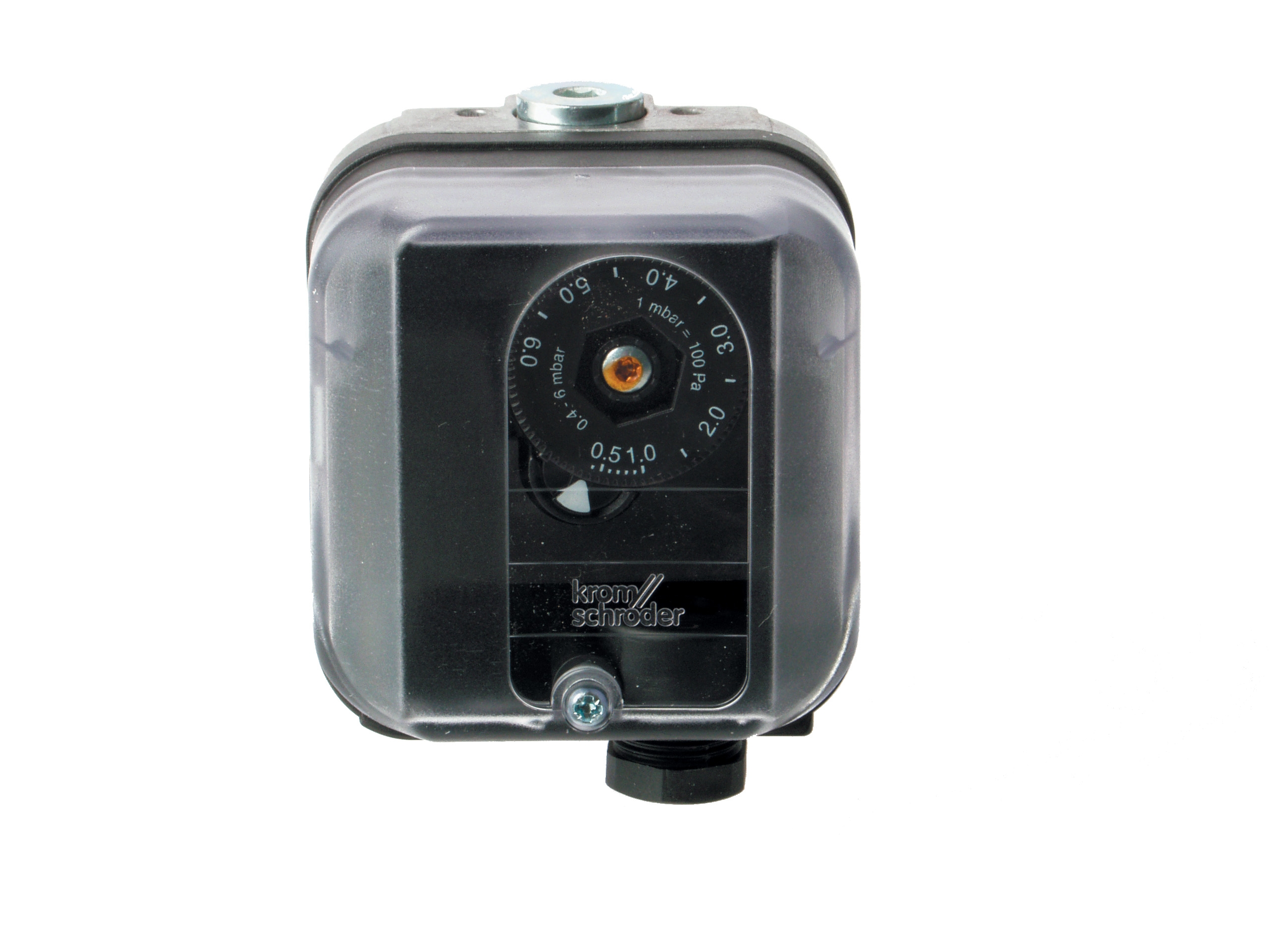
The Kromschroder DG 50U/6 pressure switch rated SIL 3 / Performance Level e governs fuel or combustion air supply during ignition. If the pressure switch fails to close when demand is signaled, fuel cannot reach the burner even if the ignition system functions perfectly. Conversely, if the switch develops hysteresis or drift, it may allow fuel flow before combustion air is confirmed, creating a safety hazard.
Section 2: Systematic Diagnostic Procedures for Ignition Failures
Step 1: Capture and Document Fault Codes and Timing Data
When an ignition failure occurs, the control module typically logs:
- Time elapsed before flame detection was expected
- Whether the flame detector signal ever appeared (even momentarily)
- Pressure switch state transitions (open → closed → open)
- Number of ignition attempts before lockout
Step 2: Visual Inspection and Sensor Accessibility
Due to thermal cycling and thermal shock in Southeast Asia's high-humidity environment, flame detectors accumulate:
- Soot and combustion residue on the optical surface
- Moisture in the cable gland during cool-down cycles
- Corrosion on the mounting bracket or terminal lugs
For the Siemens QRB4A-B036B40B, the two-wire thermoplastic cable is vulnerable to cracking near the terminal end if the detector vibrates against the mounting bracket. Flex the cable gently along its length and listen for internal crackling (indicates internal conductor breakage).
Step 3: Flame Detector Signal Strength Test
Without a dedicated flame detector tester (available from Siemens or third-party suppliers), perform a field verification:
1. Dark-room test: With the burner de-energized and isolated, hold a lighter or small open flame 50 mm from the detector lens (simulate flame presence). The control module should log a flame signal or trigger a "flame detected during lockout" alarm. If no response occurs, the detector is likely defective.
2. Cable continuity test: Using a multimeter, measure resistance between the two conductors at the detector terminals and at the control module input. The two-wire cable should show less than 2 ohms DC resistance. If resistance exceeds 10 ohms, the cable is compromised.
3. Insulation resistance test: Measure insulation resistance (DC 500V megohm test) between the two conductors and ground (the mounting bracket). Should exceed 100 megohms. Values below 50 megohms indicate moisture ingress and warrant cable replacement.
When to replace: If any of the above tests fail, or if the detector has logged more than 3 ignition failure events within one week, replace the flame detector. The Siemens Cell QRB4A-B036B40B is a standard replacement offering the necessary SIL rating and thermal robustness for Southeast Asian industrial environments.
Step 4: Pressure Switch Verification
The Kromschroder DG 50U/6 pressure switch must reliably close when fuel or combustion air demand is signaled, and open when demand ceases. Hysteresis (the difference between close and open setpoints) should not exceed ±5% of the nominal setpoint.
Action: Isolate the burner and measure DC voltage across the pressure switch terminals during ignition demand. The voltage should drop to near 0V when the switch closes (confirming electrical continuity). If voltage remains high or fluctuates, the switch may be sticking or the internal contact may be pitted.
For critical applications, use a secondary pressure transducer (0–10 bar range) connected downstream of the pressure switch to confirm that fuel or air pressure actually rises when the switch is commanded closed. A pressure switch may show electrical closure while the internal valve seat is damaged and leaking.
Step 5: Combustion Air and Fuel Supply Assessment During Ignition
Ignition failures often occur because insufficient combustion air reaches the burner during the critical 2–3 second ignition window. In Southeast Asia's tropical climate, air intake filters clog rapidly with humidity-bound dust.
Action: Verify that the air damper moves freely to the fully open position when ignition is commanded. Use a light to inspect the air intake filter; soot accumulation should not exceed 2 mm. Install a temporary pressure transducer at the burner air inlet to confirm that combustion air pressure rises within 1 second of ignition command.
For fuel systems, confirm that fuel pressure reaches the burner nozzle within 2 seconds by measuring the fuel line pressure at the nozzle inlet during an ignition attempt. For the heavy oil burners like the FBR KN 350/M, fuel must be preheated to the correct viscosity (typically 30–50 cSt at burner inlet) before ignition will succeed. If fuel is too viscous at startup, the flow reaches the nozzle too slowly for proper atomization and flame establishment.
Section 3: Component Specification and Replacement Strategy
Flame Detector Replacement and Optical Alignment
When replacing a failed flame detector, ensure that the new unit maintains the same optical axis to the flame region. Misalignment of just 10–15 mm can result in weak or intermittent signal.
Key specification requirements:
- UV/IR cell type (UV cells are more resistant to infrared background radiation in industrial environments)
- Thermal rating: minimum 65°C ambient capability for Southeast Asian ambient
- Cable type: thermoplastic-insulated, rated for repeated thermal cycling (the Siemens QRB4A-B036B40B meets these criteria with its two-wire construction and high-temperature insulation)
- Mounting hole spacing: confirm 36 mm spacing for Siemens detectors; 50 mm for generic alternatives
Pressure Switch Recalibration and Replacement
If the Kromschroder DG 50U/6 has logged multiple ignition failures and field tests confirm stuck operation, do not attempt field calibration. Instead:
1. Isolate the burner electrically and mechanically.
2. Disconnect the switch from fuel/air supply lines (note the inlet and outlet ports).
3. Document the electrical connections (common, normally-open, normally-closed contacts).
4. Return the switch to 3G Electric for factory recalibration or replacement. Recalibration at the factory (performed by Kromschroder service centers) restores the switch to SIL 3 certification; field adjustment invalidates SIL compliance.
5. Install a new or factory-recalibrated switch with identical setpoint configuration.
As a maintenance best practice, schedule pressure switch replacement every 5 years or after 10,000 burner operating hours in high-cycle applications (multiple start-stop events daily).
Industrial Gas Burner Commissioning Post-Repair
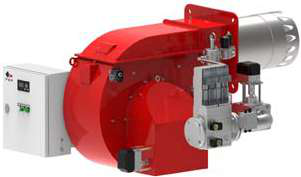
After replacing a flame detector or pressure switch, the entire ignition sequence must be re-commissioned. The FBR HI-GAS P650/M CE TL and FBR HI-GAS P1500/M CE TL require specific commissioning steps:
1. Air purge cycle: Allow combustion air to flow for 30 seconds before first ignition attempt (removes any fuel-air mixture remaining from prior operation).
2. Low-fire ignition test: Command the burner to low-fire mode (typically 30–40% capacity) for the first startup. This allows stable flame establishment before modulation to higher load.
3. Flame stability observation: Monitor the flame visually (if sight glass available) or via control module diagnostics for at least 60 seconds. Flame color should transition from yellow (ignition transient, soot rich) to blue (stable combustion) within 5–10 seconds.
4. Pressure and temperature verification: If burner is installed in a heating loop, confirm that outlet temperature rises steadily and pressure remains stable (does not oscillate or spike).
Section 4: Preventive Maintenance to Reduce Ignition Failures
Monthly Inspection Protocol
- Visually inspect the flame detector lens for soot accumulation. Light soot (white/gray) is normal; heavy soot (black, >2 mm thick) requires cleaning.
- Listen to ignition attempts and confirm the characteristic spark or glow-plug activation noise. Absence of ignition sounds indicates transformer or spark plug failure.
- Record the number of ignition attempts required for flame establishment. If this number increases from 1–2 to 3–4+ attempts, flame detector contamination or pressure switch hysteresis is developing.
Quarterly Procedures
- Remove and clean the flame detector lens with isopropyl alcohol and a lint-free cloth. Allow to dry completely before reinstallation.
- Inspect the burner air intake filter and fuel supply line connections. Tighten any loose connections (vibration loosening is common in high-vibration industrial environments).
- Measure and log the fuel or combustion air pressure during idle (no ignition demand) and during ignition command. Pressure should remain constant at idle and rise smoothly when demand is signaled.
Annual Tasks
- Schedule pressure switch recalibration or replacement. A 5-year replacement interval ensures SIL compliance and reduces unexpected failures.
- Inspect burner internal tube surfaces (with burner isolated) for corrosion or scaling that may degrade heat transfer or obscure flame visibility.
- Test the entire ignition sequence in low-fire mode and record the time from ignition command to stable flame detection. Nominal time is 2–4 seconds; times exceeding 6 seconds indicate developing sensor or fuel delivery issues.
Conclusion
Ignition failures in industrial Burners & Combustion systems are highly disruptive but systematically diagnosable. By following the diagnostic procedures outlined above—capturing fault logs, inspecting and testing sensors, verifying pressure switches, and assessing combustion air and fuel supply—maintenance teams can identify root causes within 1–2 hours rather than 1–2 days of trial-and-error troubleshooting.
Proper component selection (flame detectors like the Siemens QRB4A-B036B40B rated for industrial thermal cycling, pressure switches like the Kromschroder DG 50U/6 certified to SIL 3) and preventive maintenance (monthly lens cleaning, quarterly inspections, annual recalibration) dramatically reduce the frequency and severity of ignition events.
3G Electric's 35+ years of experience distributing industrial burners and combustion controls throughout Southeast Asia equips us to supply replacement components with next-business-day delivery across the region, and to provide technical support for commissioning and troubleshooting. When ignition failures occur, rapid access to certified replacement parts and technical guidance minimizes downtime and production loss.