Introduction: Why Commissioning Matters for Burners & Combustion Systems
Burners & combustion systems represent some of the most critical equipment in industrial and commercial facilities. Whether powering steam boilers, process heaters, or large-scale thermal applications, proper commissioning determines reliability, fuel efficiency, and regulatory compliance from day one.
3G Electric has supplied industrial burner components and control systems globally for over 35 years, and we've learned that rushed or incomplete commissioning is the leading cause of early failures, nuisance shutdowns, and safety incidents. This guide shares practical commissioning procedures that maintenance teams can apply immediately, whether installing new equipment or recommitting existing systems after maintenance.
Unlike generic installation manuals, this article focuses on the real-world steps your team needs to verify that flames ignite safely, pressures hold stable, and flame detection systems respond correctly before full operation.
Section 1: Pre-Commissioning Inspections and Documentation
Physical Equipment Verification
Before energizing any burner system, conduct a thorough physical inspection:
- Fuel supply integrity: Inspect fuel lines, oil filter housings, and gas trains for leaks, kinks, or corrosion. Use soapy water on gas connections; audible hissing indicates leakage requiring repair before startup.
- Electrical connections: Verify all terminal blocks, control wiring, and flame detector cables are secure and rated for the operating environment. Check for moisture ingress in electrical cabinets, especially in humid or coastal locations.
- Burner positioning: Confirm the burner sits at correct furnace/boiler alignment. Misalignment causes flame impingement on walls, poor combustion, and premature component wear.
- Flame path clearance: Ensure the flame tube and refractory chamber are free of debris, old gasket material, and obstructions that might block flame signal detection.
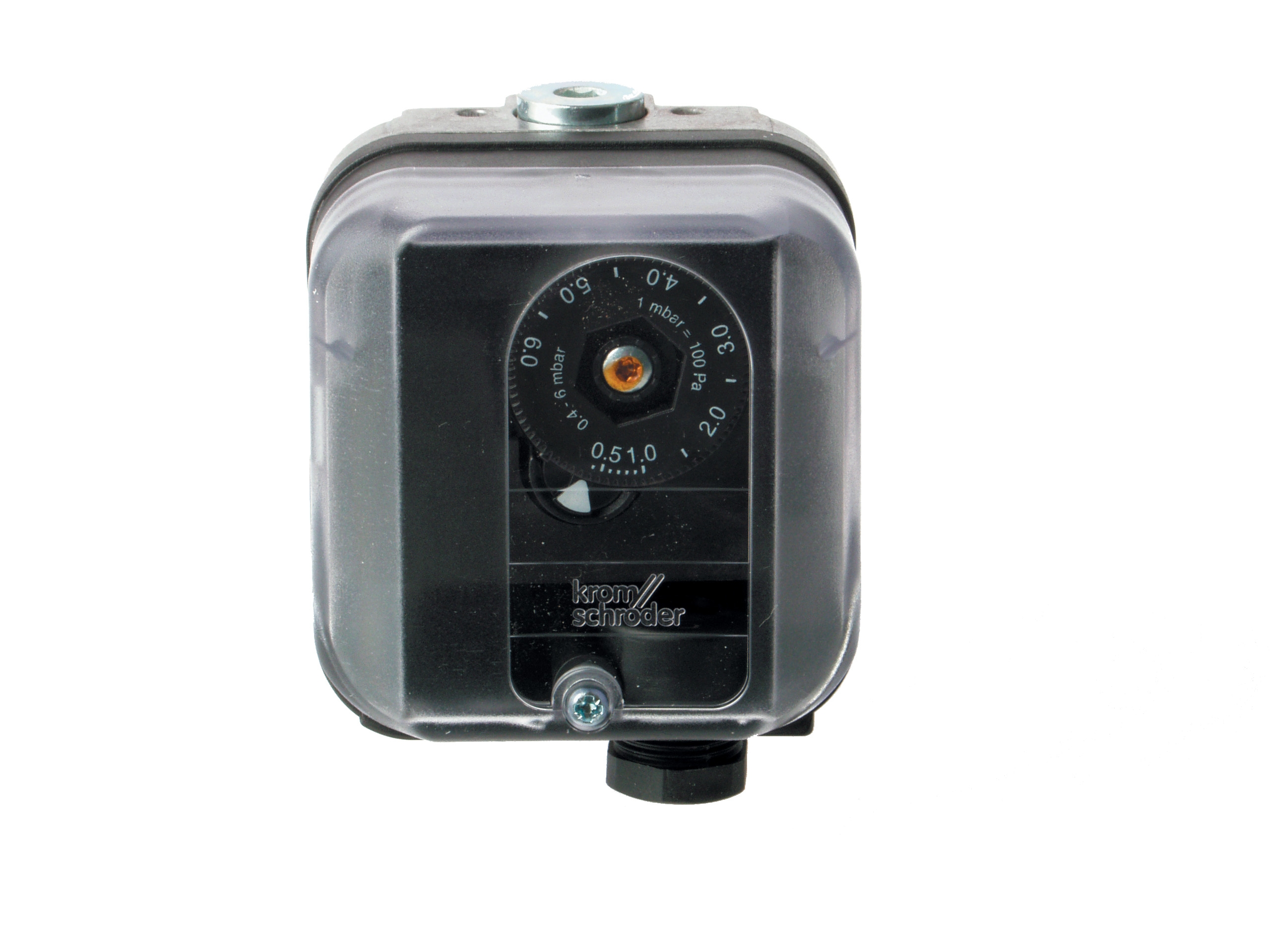
- Pressure switch mounting: Verify the Kromschroder DG 50U/6 pressure switch is mounted horizontally (unless otherwise specified) and the pressure tap is clean and connected to the correct gas pressure point.
Safety Device Documentation
Create a commissioning log that records:
- Model numbers and serial numbers of all components
- Calibration dates for pressure switches and flame detectors
- Previous maintenance history (if applicable)
- Fuel type, design pressure, and flow rate specifications
- Expected ignition delay times and flame signal characteristics
This documentation becomes invaluable for troubleshooting and regulatory audits.
Section 2: Step-by-Step Startup and Ignition Sequences
Initial Setup (No Fuel Supply)
1. Energize controls without fuel supply: Turn on electrical power to the burner control unit. Most systems enter a purge cycle that pre-energizes the igniter and any pilot gas solenoids.
2. Listen for solenoid clicks: Verify that gas solenoid valves click audibly when energized. Silent solenoids indicate wiring faults or failed coils requiring replacement before proceeding.
3. Confirm igniter glow: If using an electrode igniter, verify a visible orange glow appears within 2–3 seconds. If the igniter doesn't glow, check 240V supply at the igniter terminal and verify the igniter element isn't cracked or contaminated with oil residue.
4. Observe flame detector signal: With the Siemens QRB4A-B036B40B flame detector in place (but no flame), confirm the control unit does NOT receive a false flame signal. False signals indicate contaminated optics or incorrect wiring polarity.
Fuel Introduction and Ignition
5. Slowly open fuel supply valve: If using oil fuel, crack the fuel supply valve and allow the line to vent trapped air for 10–15 seconds before fully opening. Trapped air causes ignition delay and hard starting.
6. Initiate burner startup command: Press the start button or send the startup signal. The sequence should follow this order:
- Blower runs for a preset purge period (typically 15–30 seconds)
- Igniter energizes
- Fuel solenoid valve opens
- Flame should appear within 3–5 seconds (consult equipment manual for exact parameters)
7. Observe initial flame characteristics: The flame should be steady, bright orange (for gas) or yellow-white (for oil), and centered in the flame tube. Flickering or delayed ignition indicates fuel supply problems or igniter weakness.
8. Monitor flame signal: The control unit should receive continuous flame signal feedback. If flame detection drops within the first 10 seconds, the system initiates a lockout—a normal safety response. Never override lockout sequences during commissioning.
Stabilization and Modulation Check
9. Allow 30-second run-in period: Let the burner stabilize at ignition setting without making adjustments. Combustion gas temperatures and pressures need time to reach steady state.
10. Verify low-fire and high-fire operation: If the burner is modulating (two-stage or proportional), confirm it transitions smoothly from low to high fire without hesitation, flame extinction, or pressure spikes.
11. Check pressure stability: Monitor the gas or oil supply pressure during operation. Pressure should remain within ±10% of design specification. Fluctuating pressures indicate regulator issues or fuel supply problems.
Section 3: Safety Device Verification and Calibration
Pressure Switch Function Testing
The Kromschroder DG 50U/6 pressure switch is a critical safety device that shuts down the burner if fuel pressure drops below minimum (flame failure) or exceeds maximum (overpressure risk).
Low-pressure switch test:
- Note the current gas supply pressure reading on the control unit's pressure gauge
- Slowly restrict the fuel supply by closing the fuel valve incrementally
- The control unit should initiate a shutdown when pressure drops approximately 0.1–0.2 bar below operating pressure
- If shutdown doesn't occur, the pressure switch may require replacement
- Record the exact shutdown pressure for maintenance records
- With burner running at full fire, carefully increase fuel supply pressure by opening the supply valve
- The system should lock out if pressure exceeds the high-limit setting (typically 0.5–1.0 bar above operating pressure)
- Document the lockout pressure
- Never force pressure above safe limits; if the high-limit switch doesn't respond, stop testing and contact the equipment manufacturer
Flame Detector Response Testing
The Siemens QRB4A-B036B40B flame detector must respond within milliseconds to flame presence and absence.
Response time verification:
- With the burner running at stable operation, cover the flame detector lens with a non-flammable material (aluminum foil or a brass plate)
- The control unit should initiate shutdown within 2–5 seconds (exact response time depends on control module settings)
- Remove the cover; the burner should not restart automatically (safety design prevents nuisance recycling)
- If response is delayed beyond 10 seconds, the detector may be contaminated, misaligned, or failing
- Inspect the detector lens for oil residue, ash, or condensation
- If contaminated, carefully clean the lens with a dry, lint-free cloth or lens cleaner appropriate for the detector type
- Do not use solvents that may damage optical coatings; check the manufacturer's guidance
Section 4: Performance Optimization and Handover
Air-Fuel Ratio Optimization
Once the burner ignites reliably and safety devices respond correctly, optimize combustion efficiency:
- Observe flame color and pattern: A bright, steady flame indicates good air-fuel balance. Blue-tinged flames suggest excess air; sooty yellow flames indicate incomplete combustion.
- Measure flue gas temperature: If available, use a digital flue gas probe to measure exhaust temperature. Higher than design specification (typically 150–200°C above incoming air) may indicate poor air supply or fouled heat exchanger surfaces.
- Monitor for flame noise: Burners operating with correct air-fuel ratio produce a steady roar. High-pitched whistling or rumbling indicates air supply obstruction or combustion instability.
Modulation and Firing Rate Adjustment (Dual-Stage and Proportional Burners)
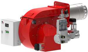
For burners like the FBR HI-GAS P1500/M CE TL or FBR KN 350/M dual-fuel burner, verify smooth modulation:
- Low-fire setting: Reduce the heating load (or use the control unit's manual adjustment) to bring the burner to low-fire position. Record the fuel flow rate and ensure it remains stable for at least 2 minutes.
- Transition to high-fire: Gradually increase load. The burner should transition smoothly without flame extinction, pressure surges, or ignition delays.
- High-fire stability: At maximum fire, confirm pressure and flame quality remain stable over a 5-minute run period.
- Document all settings: Record low-fire and high-fire pressures, temperatures, and fuel flow rates. This baseline is essential for future troubleshooting.
Final Safety and Regulatory Checks
- Verify emergency shutdown: Confirm that pressing the emergency stop button (E-stop) shuts down the burner and locks out further operation until the E-stop is reset and a new start command is issued.
- Test manual fuel cutoff: Ensure the manual fuel isolation valve operates smoothly and fully closes fuel flow when needed for maintenance.
- Document compliance: Create a commissioning certificate that records all test results, dates, technician names, and any deviations from specification. This documentation supports regulatory compliance in jurisdictions requiring certified burner commissioning.
- Provide operation manual: Leave clear written procedures for daily startup, shutdown, and emergency procedures with the facility operator.
Conclusion: Ongoing Commissioning Support
Successful commissioning establishes a foundation of reliability, but maintenance doesn't end at startup. 3G Electric recommends quarterly pressure switch verification, semi-annual flame detector cleaning and alignment checks, and annual full-system commissioning reviews—especially for critical applications.
Our global supplier network stocks replacement pressure switches, flame detectors, and burner components across multiple brands. When your team encounters commissioning challenges, we can provide troubleshooting support and expedited parts delivery to minimize downtime.
Commissioning done right saves money, prevents accidents, and extends equipment life. Use this guide as your team's standard procedure, adapt it to your specific equipment, and share results with your management and regulatory teams.