Understanding Fuel Supply Chain Failures in Burners & Combustion Systems
With over 35 years of experience as an industrial equipment distributor, 3G Electric has documented that fuel supply chain failures account for the majority of premature burner shutdowns across Southeast Asian facilities. Burners & Combustion systems depend on continuous, clean fuel delivery at precise pressures and temperatures. When this chain breaks—whether through filter saturation, line blockages, fuel degradation, or pressure regulation failure—the result is immediate combustion instability, failed ignition sequences, or complete system lockout.
Unlike flame detection failures or electrode maintenance issues, fuel supply problems often develop gradually, making them difficult to diagnose without systematic testing protocols. Industrial professionals frequently misattribute fuel supply failures to electrical control issues or safety relay malfunctions, leading to unnecessary component replacements and extended downtime.
This guide focuses on practical diagnostic procedures for identifying and resolving fuel supply chain failures in Burners & Combustion systems operating across Singapore's industrial landscape—from district heating networks to process heating in food production, petrochemicals, and manufacturing facilities.
Section 1: Fuel Line Pressure Diagnostics and Blockage Identification
Baseline Pressure Measurement Protocol
Before troubleshooting, establish the correct baseline operating pressure for your specific burner. Most commercial oil burners operate at 10–15 bar at the nozzle inlet, while gas burners typically require 50–200 mbar depending on burner type and modulation range.
Step 1: Install Pressure Test Points
Locate or install pressure measurement ports at three critical points:
- Main fuel pump discharge (primary pressure)
- Burner inlet (secondary pressure after line losses)
- Post-filter pressure (diagnostic point for filter saturation)
With the burner running at full firing rate, record pressures at all three points using calibrated analog or digital pressure gauges. Document these values in your maintenance log. Pressure drop between discharge and burner inlet should not exceed 1–2 bar for oil systems or 10% of supply pressure for gas systems.
Step 3: Perform Dynamic Pressure Cycling
During a normal start/stop cycle, pressure should rise to operating setpoint within 3–5 seconds and stabilize without oscillation. If pressure overshoots (exceeds setpoint by >2 bar) or oscillates continuously, suspect failing pressure regulation or air leaks in the fuel line.
Identifying Blockage Locations
A sudden pressure drop at the secondary measurement point (burner inlet) while primary pressure remains stable indicates blockage between the pump and burner. Systematic isolation identifies the exact location:
Blockage Isolation Procedure:
- With pump running at idle pressure (2–3 bar), manually open the fuel filter drain valve
- If fuel flows freely with strong spray pattern, the pump and primary lines are clear
- If fuel drips weakly or not at all, suspect blockage in the fuel tank pickup line or suction strainer
- Close the drain valve; stop the pump and disconnect the burner inlet fuel line
- Restart the pump briefly and observe flow at the disconnected line
- Strong flow indicates secondary line blockage; weak flow indicates pump discharge or filter blockage
This procedure typically isolates the problem within one or two steps, eliminating unnecessary filter replacements.
Temperature Effects on Fuel Supply Pressure
Singapore's tropical climate creates unique pressure challenges. Ambient temperatures averaging 28–32°C and higher in mechanical rooms reduce fuel viscosity in oil systems and can cause vapor lock in diesel burners.
Temperature Compensation Protocol:
- Record fuel temperature at the pump intake using a thermometer or temperature sensor
- Compare operating pressure against the burner manufacturer's temperature-corrected pressure curve
- If pressure drops more than 1 bar when temperature rises 5°C, suspect vapor formation in the fuel line
- Corrective action: Install fuel line insulation or relocate fuel lines away from hot equipment; consider a fuel cooler for systems operating above 45°C
Section 2: Filter Saturation Detection and Service Intervals
Pressure Differential Monitoring for Filter Condition Assessment
The pressure difference between the upstream and downstream filter ports directly indicates saturation level. Many blockage problems originate from filters operating beyond their service life, even though visual inspection appears acceptable.
Filter Condition Assessment:
- New filter: 0.1–0.3 bar pressure differential at full pump flow
- Service needed: 0.8–1.2 bar differential (approximately 80% saturation)
- Replace immediately: >1.5 bar differential or if primary burner pressure drops below setpoint
If your burner lacks downstream filter pressure ports, install a temporary gauge on the return line with the pump running. The suction side gauge (typically 0–1 bar scale) will show negative pressure proportional to filter saturation. Readings below -0.5 bar indicate urgent replacement.
Identifying Incorrect Filter Selection
Singapore's humid climate and coastal marine environment accelerate fuel tank contamination. Using undersized filters (high flow capacity, coarse filtration) causes rapid saturation and allows particulate contamination into nozzles.
Filter Selection Verification:
- Locate the filter micron rating and flow capacity on the canister label
- Cross-reference against the burner fuel pump flow rate (typically 0.5–2 gallons per minute for oil burners)
- Oil burner filters should be 10–25 microns absolute; gas burners typically use 50 microns
- If filter capacity exceeds pump flow by >50%, saturation occurs rapidly; downsize to appropriate capacity
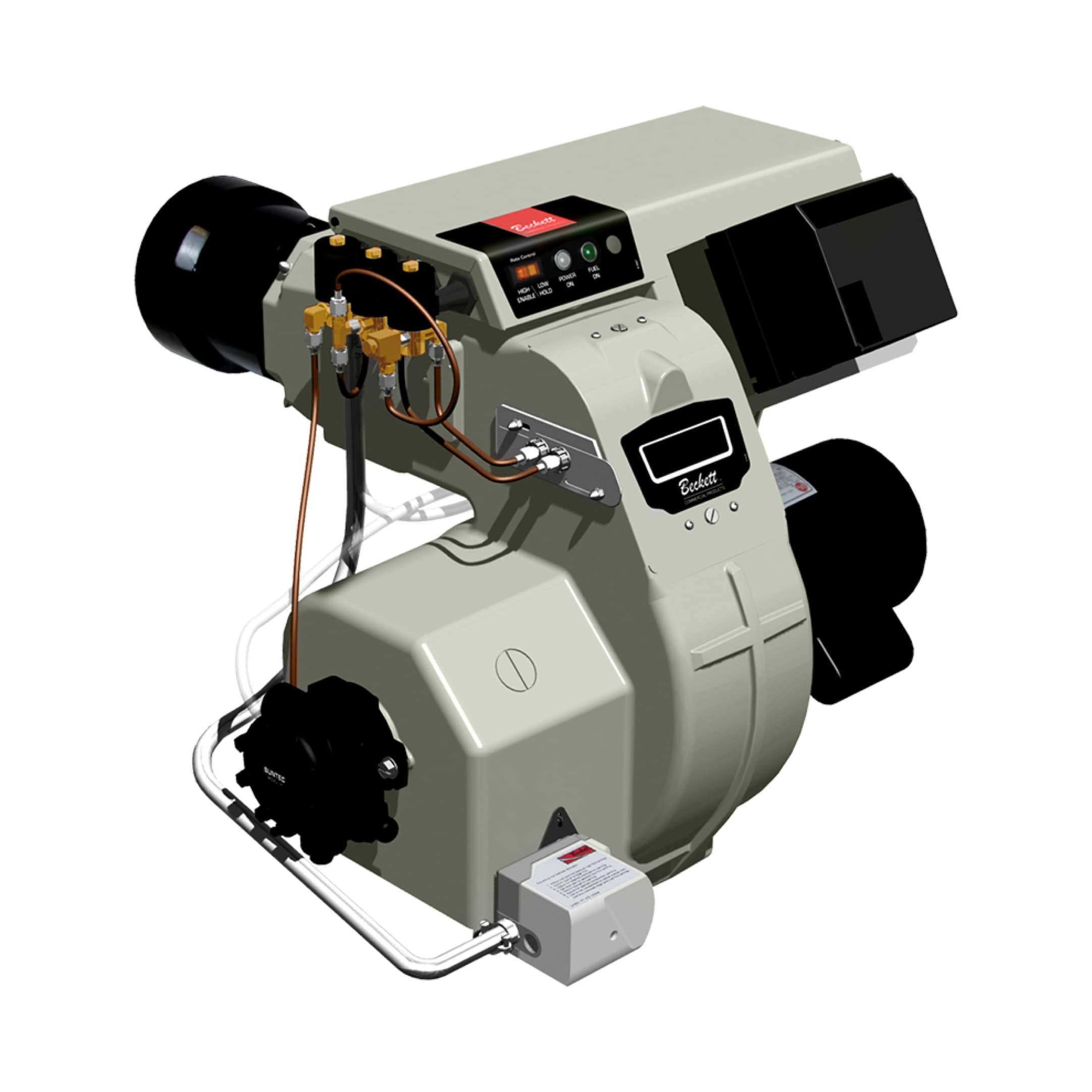
For systems using Beckett CF3500 oil burners (17–35 GPH rated capacity), a 100-micron filter designed for portable equipment will block within 10 operating hours in typical Singapore industrial environments. Specify 10-micron filters rated for the full burner flow rate.
Service Interval Optimization
Establish a condition-based service schedule rather than fixed time intervals:
- Service filter when differential pressure reaches 1.0 bar (measure monthly)
- Service immediately if particulate appears in fuel sample or if pressure fluctuates during operation
- In high-contamination environments (fuel tanks >10 years old, outdoor storage), service every 50–100 operating hours
- Change filter at season start-up before continuous operation begins
Section 3: Fuel Quality and Supply Chain Contamination Management
Identifying Fuel Degradation and Water Content Issues
Fuel quality deterioration is endemic in Singapore's maritime industrial zones where high humidity, temperature fluctuations, and long storage periods contaminate even properly sealed tanks. Water ingress causes nozzle clogging, corrodes fuel system components, and promotes bacterial growth in tanks.
Visual Fuel Quality Assessment:
- Extract a fuel sample from the tank bottom using a fuel sampling valve (install one if absent)
- Observe color: degraded fuel appears dark brown or black; fresh fuel is golden to light brown
- Check for sediment: pour sample through white filter paper; dark residue indicates tank contamination
- Smell test: acidic or sour odor indicates microbial growth; musty odor indicates water contamination
- Use water-detection paste available from industrial suppliers (turns color in presence of water)
- If water detected, drain tank completely and refill with fresh fuel
- Install a water drain valve at the tank bottom for routine maintenance
- Consider fuel treatment additives for tanks experiencing recurring water contamination
Microbial Contamination and Bio-Sludge Formation
Bacterial and fungal colonies thrive in the water layer at tank bottoms, creating bio-sludge that blocks fuel lines and filters. This problem accelerates in humid, warm climates.
Bio-Sludge Identification:
- Black or brown gelatinous material visible in fuel sample
- Rapid filter saturation with dark, spongy deposits
- Fuel line odor similar to decomposing organic material
- Drain and flush the entire fuel tank system (pump, lines, filter, nozzle)
- Replace fuel with fresh stock from a reputable supplier
- Install a fuel polishing unit for high-value systems; this system continuously filters and dehydrates fuel during standby periods
- Add biocide treatment (fuel system sterilant) during refill for long-term tank protection
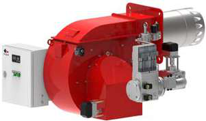
Systems using FBR HI-GAS P550/M burners or FBR gas burners in continuous operation rarely develop bio-sludge; systems with intermittent operation or extended idle periods require quarterly fuel condition assessments.
Fuel Supply Chain Documentation
Maintain records of fuel supplier, delivery dates, batch numbers, and initial quality assessments. This enables rapid identification of contamination sources—whether from supplier fuel quality, tank degradation, or in-system formation.
Section 4: Pressure Regulation Failures and Recovery Procedures
Pressure Regulator Function and Failure Modes
The fuel pressure regulator maintains constant burner inlet pressure despite variations in pump output, ambient temperature, and firing rate. Regulator failures cause either constant overpressure (nozzle damage, atomization failure) or underpressure (incomplete combustion, flame instability).
Common Failure Modes:
- Regulator stuck open: Pressure remains at 2–3 bar (pump idle pressure) despite pump running at full capacity; burner fails to start or operates at reduced output
- Regulator stuck closed: Pressure rises continuously to pump maximum (often 25+ bar) until safety relief opens; burner operates with violent pressure oscillations
- Diaphragm rupture: Regulator response becomes erratic; pressure fluctuates 2–4 bar during stable operation
- Contaminated valve seat: Regulator leaks internally; pressure drops immediately when pump stops
1. Record steady-state pressure with burner at full firing rate
2. Stop the burner and pump; record how quickly pressure drops at the gauge
3. If pressure holds steady for >30 seconds after pump stops, suspect internal leakage—replace regulator
4. If pressure drops immediately, regulator closure is functioning
5. With burner idling (pump at low flow), observe pressure stability; oscillation >0.5 bar indicates diaphragm wear
Regulator Adjustment and Calibration
Many regulators include adjustment screws for setpoint modification. Before disassembly:
Safe Adjustment Procedure:
- Record the current pressure setting
- Loosen the adjustment screw locknut by one-quarter turn only
- Turn the adjustment screw clockwise (increase pressure) or counterclockwise (decrease pressure) by small increments
- Allow 30 seconds for pressure to stabilize after each adjustment
- Lock the adjustment screw when pressure reaches target
- Verify new setpoint remains stable over 5 operating cycles
If regulator cannot be adjusted to setpoint or pressure oscillates continuously after adjustment, internal component failure has occurred—replacement is required.
Relief Valve Function and Safety Verification
The fuel pressure relief valve protects the system from dangerous overpressure if the regulator fails. Relief valves typically open at 20–25 bar for oil systems.
Relief Valve Verification:
- With pump running and regulator isolated (remove regulator temporarily for testing only), pressurize the fuel line gradually
- Relief valve should open and allow fuel to drain at the setpoint pressure (typically 20–25 bar)
- If relief valve does not open by 25 bar, or drains excessively at 15 bar, replace immediately
- Test this procedure annually or whenever regulator service is performed
Regular relief valve testing prevents catastrophic overpressure failures that can rupture fuel lines and nozzles, creating safety hazards.
Practical Application: Systematic Diagnostics for Fuel Supply Problems
The Three-Minute Field Test
When a burner fails to start or operates erratically, this quick diagnostic sequence isolates fuel supply problems in minutes:
1. Fuel pump activation: Turn on the burner; listen for pump motor running and feel for vibration at the fuel line; if no pump activity, suspect electrical failure (separate from fuel supply issue)
2. Pressure rise: Attach a pressure gauge at the burner inlet within 10 seconds of pump start; pressure should rise from 2–3 bar to 12–15 bar (oil) or 80–150 mbar (gas) within 5 seconds
3. Steady-state observation: At stable burner operation, note pressure: if within 1–2 bar of setpoint, fuel supply is adequate; if pressure oscillates more than 1 bar, suspect regulator or filter issues
If pressure fails to rise within 5 seconds, proceed to blockage isolation (Section 1). If pressure oscillates, proceed to filter assessment (Section 2).
Integration with Safety Relay Testing
Fuel supply failures often trigger flame detection relay responses because insufficient pressure prevents atomization and stable combustion. When flame detection Combutech Flame Relay CF1 issues are suspected, verify fuel supply pressure first. Insufficient pressure (below 10 bar for oil) will always cause flame failure regardless of detector function.
Similarly, UV flame detector sensitivity requires adequate combustion stability, which depends on correct fuel pressure and atomization quality. Using Combutech UV1p detection cells, confirm flame is visible to the naked eye before assuming detector malfunction.
Documentation and Trending
Maintain a fuel supply pressure log with entries at burner startup, steady-state operation, and shutdown. Over multiple weeks, pressure trends reveal:
- Rising baseline pressure: Filter saturation progressing; schedule filter service
- Declining operating pressure: Pump wear or regulator drift; plan component replacement
- Increasing oscillation: Diaphragm deterioration; accelerate regulator maintenance
- Pressure spikes during modulation: Solenoid valve response issues; coordinate with control system diagnostics
This trending data supports predictive maintenance scheduling and prevents catastrophic failures.
Conclusion
Burners & Combustion reliability in Singapore's demanding industrial environment depends on disciplined fuel supply chain management. By implementing the diagnostic procedures outlined—pressure monitoring, filter condition assessment, fuel quality verification, and regulator function testing—maintenance teams can resolve 80% of fuel supply problems within their first occurrence, eliminating the costly trial-and-error replacement cycles that characterize reactive maintenance.
3G Electric's 35+ years of experience across Southeast Asian industrial operations confirms that systematic fuel diagnostics reduce unplanned downtime by 40–60% compared to component-replacement approaches. Paired with flame detection reliability and combustion air optimization, fuel supply excellence forms the foundation of stable, efficient burner performance.
For equipment selection support, diagnostic consultation, or component sourcing, 3G Electric's technical team supports Singapore industrial professionals with genuine industrial-grade equipment and field-proven troubleshooting protocols.