Understanding the Diagnostic Workflow for Burners & Combustion Systems
When a burner fails, plant managers face immediate pressure: production stops, steam pressure drops, and every minute costs money. After 35 years distributing industrial equipment across Southeast Asia, 3G Electric has learned that the difference between a 30-minute fix and a 4-hour downtime is systematic diagnosis, not luck.
Burners & Combustion systems fail along predictable pathways. Rather than calling technicians blindly, plant managers who understand the diagnostic logic can eliminate 70% of false alarms and communicate precisely with specialists. This guide gives you the decision trees used by advanced maintenance teams.
Section 1: The Three-Layer Combustion Failure Model
Every burner failure falls into one of three categories: No Ignition, Unstable Flame, or Reduced Output. Identifying which layer you're in takes 60 seconds and determines your next steps.
Layer 1: No Ignition (System Won't Start)
The burner receives the start command but produces no flame. The problem exists in the ignition circuit (spark, fuel delivery, or safety interlocks).
- Check if the fuel pump relay is clicking (audible confirmation)
- Verify solenoid valve voltage with a multimeter (should read line voltage)
- Confirm electrode spark gap is correct (typically 3–4 mm)
- Test gas pressure at burner inlet (compare against burner nameplate specification)
If the pump runs but no spark appears, the problem is electrical. If spark appears but no fuel ignites, the problem is fuel delivery or air/fuel ratio.
Layer 2: Unstable Flame (Flame Hunting or Cycling)
The burner ignites but the flame detection system reports false signal loss, causing repeated reignition attempts. This is a flame detection and feedback loop problem, not a combustion quality issue.
- Clean the UV detector lens (dust buildup is the #1 cause in tropical climates)
- Verify the Combutech UV1p detection cell is receiving unobstructed view of the flame
- Check the Combutech Flame relay CF1 for loose connections
- Test detector-to-relay wiring continuity
- Verify flame detection recovery time meets specification (should be <50 ms for industrial burners)
If cleaning the detector stops the cycling, document it as preventive maintenance task. If cycling continues, the flame itself may be unstable (see Layer 3).
Layer 3: Reduced Output (Flame Burns but Burner Underperforms)
The flame is stable but the burner doesn't reach nameplate BTU/kW output. The problem is in fuel flow regulation, air supply, or combustion chemistry.
- Measure fuel pressure at the nozzle (compare to burner manual)
- Check air damper position (should match load demand)
- Verify fuel atomization (spray pattern should be conical, not streaky)
- Test combustion air temperature and humidity
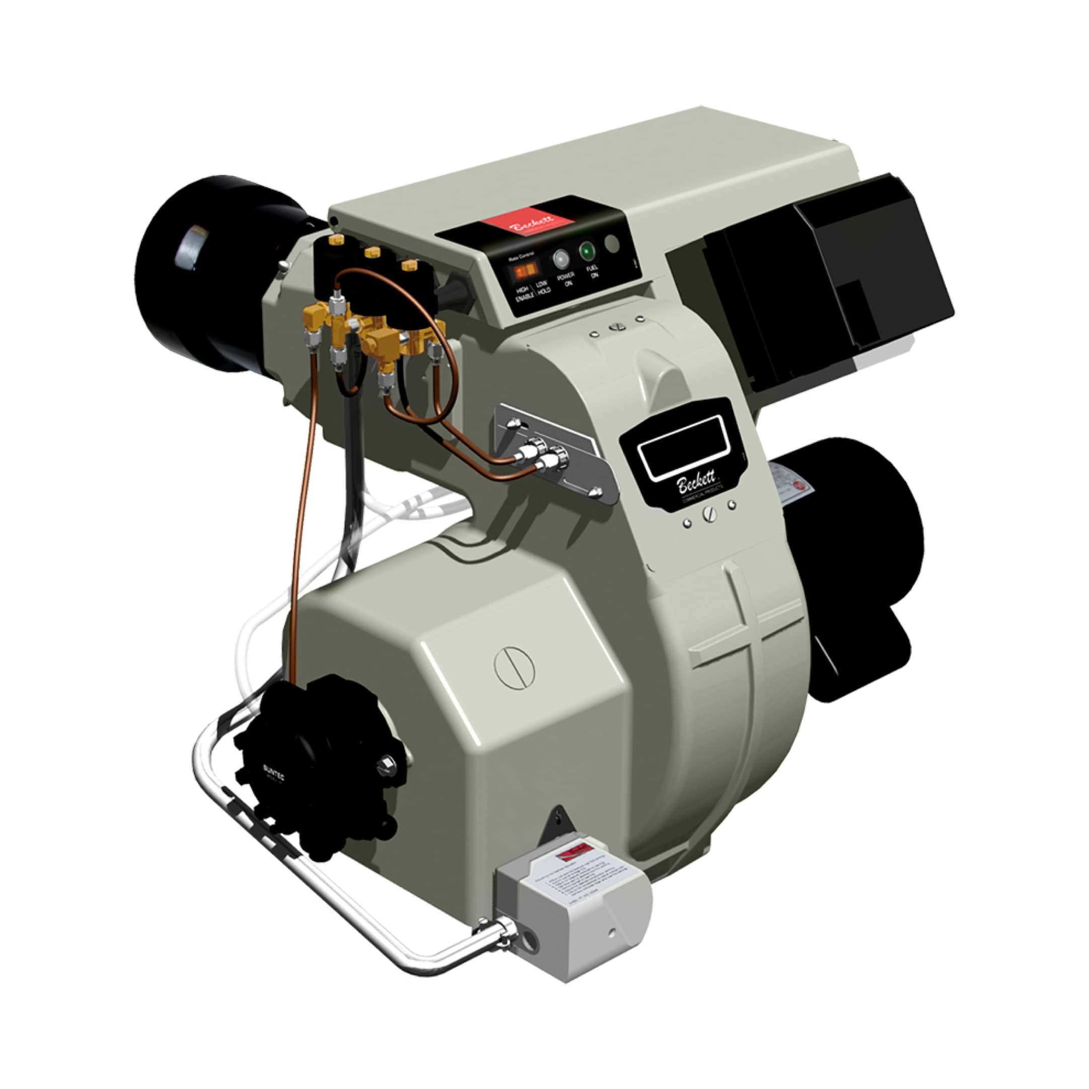
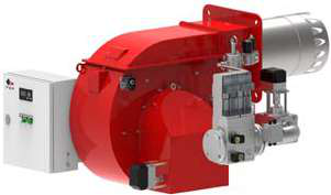
For oil burners like the Beckett CF3500, reduced output often means nozzle clogging or incorrect pump pressure. For gas burners like the FBR HI-GAS P550/M, it usually means modulation valve stuck or air supply blocked.
Section 2: Rapid-Fire Diagnostic Checklist by Symptom
Use this table to match your observed symptom to the probable root cause and first action:
| Observed Symptom | Most Likely Cause | First Check | Tools Needed |
|---|---|---|---|
| No spark, fuel pump runs | Spark electrode gap or ignition module | Measure electrode gap (3–4 mm) | Feeler gauge, multimeter |
| Spark present, no flame | Fuel pressure too low or nozzle clogged | Check pressure gauge at nozzle | Pressure gauge |
| Flame lights then goes out in 5 sec | UV detector dirty or blocked | Inspect detector lens for dust/soot | Soft brush, lens cleaner |
| Flame hunting (on-off cycling) | Flame relay sensitivity set too high | Clean detector; test relay voltage | Multimeter, brush |
| Flame stable but heat output 60% of normal | Fuel pressure low or air supply restricted | Check pump discharge pressure | Pressure gauge, manometer |
| Burner won't modulate (stays at high fire) | Modulation valve solenoid stuck | Verify 24 VDC supply to solenoid | Multimeter, clamp meter |
| Black smoke, unburned fuel odor | Air-to-fuel ratio incorrect or fuel quality poor | Check combustion air damper and fuel viscosity | Smoke tester, density meter |
Section 3: When to Escalate to Specialists
Plant managers often delay calling technicians due to cost concerns. However, certain conditions must be escalated immediately to avoid equipment damage:
Escalate Immediately (Stop the Burner):
- Flame detection system fails to reset after manual shutdown (indicates safety circuit fault)
- Oil burner produces white smoke or fog (unburned fuel entering exhaust—fire risk)
- Gas burner produces yellow/orange flames instead of blue (incomplete combustion, possible CO generation)
- Fuel leak detected at nozzle, pump, or solenoid connections
- Temperature inside burner housing exceeds 200°C at inlet (indicates blocked air supply)
- Burner requires more than 3 ignition attempts to establish flame
- Heat output has declined 15% despite normal fuel pressure
- Excessive vibration from burner motor or pump
- Electrode erosion visible (gap has increased to >5 mm)
- Fuel filter pressure drop exceeds 0.5 bar
Before technicians arrive, record:
- Time burner last ran successfully
- Fuel tank level and condition (water, debris)
- Any recent changes (new fuel supplier, temperature swings, humidity spikes)
- Exact error codes or relay click patterns
- Current meter readings (pressure, voltage, current draw)
This information cuts diagnostic time by 50% and prevents unnecessary component replacement.
Section 4: Preventive Maintenance to Reduce Emergency Failures
With 35+ years of experience in Southeast Asia, 3G Electric has seen that tropical humidity, inconsistent fuel quality, and extended run hours create predictable wear patterns. A simple monthly checklist prevents 80% of emergency calls:
Monthly (15 minutes):
- Visually inspect electrode for rust or erosion
- Check fuel tank for water accumulation (drain valve at bottom)
- Wipe UV detector lens with soft brush
- Listen for unusual pump noise during operation
- Clean fuel strainer/filter element
- Measure and document fuel pressure (at high and low fire)
- Verify flame detection response time using relay test function
- Inspect all electrical connections for corrosion
- Recalibrate flame detection relay sensitivity (if adjustable)
- Perform complete shutdown/restart cycle to test safety interlocks
- Check electrode gap and adjust if needed
- Test solenoid valve response with multimeter
For systems using the FBR HI-GAS P550/M CE TL or Beckett CF3500, document all maintenance in the equipment log—this creates a failure history that helps specialists predict what will fail next.
Climate Consideration for Southeast Asia:
High humidity and salt air (coastal facilities) accelerate electrode corrosion and detector optical contamination. In these environments, reduce maintenance intervals by 25%. Use silica gel packs inside control cabinets and specify stainless steel hardware for all replacements.
Section 5: Common Misconceptions That Waste Time
"If the flame looks yellow, the burner is dirty." — Actually, yellow flame in gas burners usually means excess air (too much oxygen), not dirt. Check air damper position first.
"I should adjust the fuel pressure higher to get more output." — Excessive pressure causes poor atomization and wasted fuel. Always verify the burner manual specification first. 3G Electric's suppliers design burners with specific pressure ranges; exceeding them creates problems, not power.
"The detector must be failing if the flame won't stay lit." — In 90% of unstable flame cases, the flame itself is defective (poor atomization, low fuel flow, insufficient air). The detector is correctly identifying a bad flame. Don't replace the detector; fix the flame.
"Frequent reignition is normal for old burners." — It's not. Reignition cycles indicate the flame detection circuit is oversensitive or the flame is unstable. Either condition should be investigated.
Troubleshooting Example: Real Plant Scenario
Situation: A Singapore food processing plant's burner producing steam for cooking kettles suddenly produces only 60% of normal heat. The flame looks stable, no visible problems.
Plant Manager's Rapid Diagnosis (10 minutes):
1. Check fuel tank level → Normal
2. Listen for pump operation → Pump running
3. Observe flame color → Blue and stable (not yellow, not flickering)
4. Measure fuel pressure at nozzle → 4.0 bar (burner manual specifies 4.5–5.0 bar for this model)
Conclusion: Fuel pressure low. Probable cause: fuel filter clogged.
Action: Replace fuel filter cartridge ($45, 15 minutes labor). Test: Heat output returns to 95% of normal.
Without the Diagnostic Approach: Plant manager might have assumed burner failure, called technician immediately, received bill for $400 service call + component replacement, losing 6 hours production.
This type of savings—financial and operational—comes from understanding where in the system the failure exists, not just that it exists.
Final Guidance: Building Your Plant's Burner Knowledge
3G Electric has supplied industrial burners and controls across Southeast Asia since 1990. We've learned that plants with the best uptime records aren't those with the newest equipment—they're the ones where plant managers and maintenance technicians understand the diagnostic logic.
Keep burner manuals in an accessible digital folder. Train at least two team members on the three-layer failure model. Document every service event. And when you're unsure whether to call a technician, err on the side of caution—safety is non-negotiable in burner systems.
The flowcharts and decision trees in this guide are designed for you to use independently. Use them to stabilize your plant and communicate clearly with specialists when you need them.