Understanding Measurement & Detection Equipment in Industrial Operations
Measurement & Detection systems form the backbone of industrial monitoring, yet procurement engineers often struggle when these critical instruments fail unexpectedly. Over 35 years, 3G Electric has observed that approximately 60% of measurement device failures stem from preventable issues—incorrect installation, environmental exposure, or simple calibration drift rather than hardware defects.
This troubleshooting guide focuses on the three most common Measurement & Detection categories affecting global industrial facilities: temperature monitoring thermometers, pressure expansion systems, and electrical diagnostic multimeters. Understanding how to diagnose failures in these areas helps procurement teams make faster repair-versus-replace decisions and reduces costly downtime.
Diagnosing Temperature Thermometer Problems
Common Temperature Measurement Failures
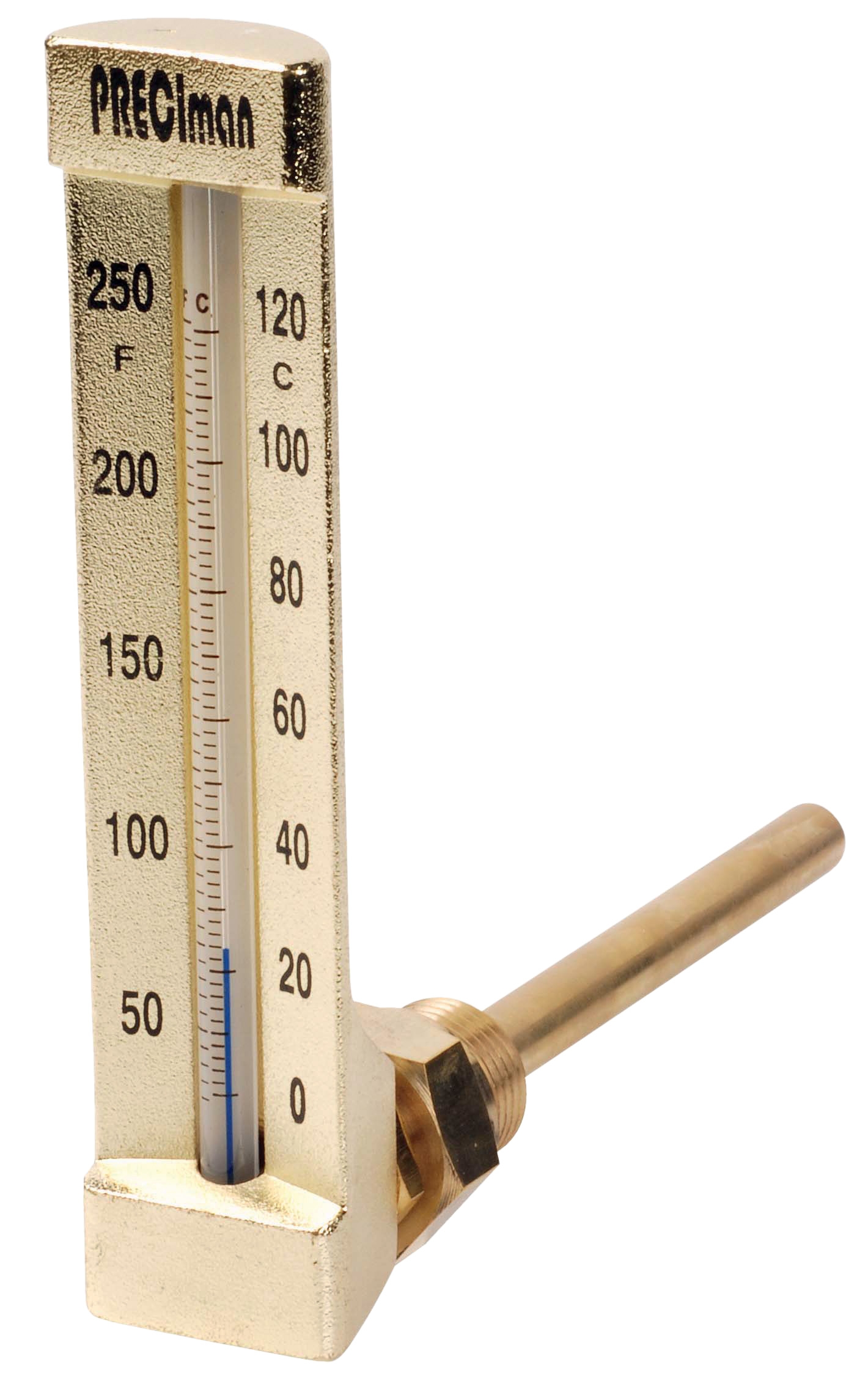
Thermometers used in industrial applications—whether axial units like the CBM Axial thermometer D65 -40/+40°C with thermowell, vertical variants like the CBM Green vertical thermometer D80 -30/+50°C, or immersion models like the CBM Industrial thermometer 0/+50°C immersion 63—experience specific failure patterns.
Reading Inconsistencies: The most frequent issue is erratic or frozen dial readings. This typically indicates:
- Liquid expansion fluid leakage inside the thermometer stem, causing the needle to stick or move unpredictably
- Air bubbles trapped in the sensing bulb, which creates false high-temperature readings
- Thermowell obstruction where sediment or corrosion blocks thermal contact between the measured medium and the sensing element
Examine the thermometer dial for visible cracks or fluid seepage around the stem. Check the thermowell (the protective tube housing the bulb) for external corrosion, scaling, or physical damage. If the glass face is clouded, internal condensation suggests a seal failure.
Step 2: Response Test
Immerse the thermometer bulb in warm water (not exceeding the upper temperature range) and observe needle movement. A properly functioning thermometer should respond within 30-60 seconds. If the needle moves sluggishly or remains stationary:
- The internal bellows mechanism may be compromised
- The sensing bulb may have ruptured
- The connection between bulb and stem may be broken
Compare readings against a known reference (ice water at 0°C and boiling water at 100°C for standard ranges). Systematic errors—readings consistently 2-3 degrees high or low across the range—indicate calibration drift. Most industrial thermometers tolerate ±2% accuracy; beyond this, replacement becomes cost-effective.
When to Replace vs. Repair
For the axial thermometer and vertical models, internal fluid leakage or bent sensing bulbs cannot be field-repaired. Thermowell cleaning may resolve sediment issues, but if the sensing element itself is faulty, procurement teams should budget for replacement units. The investment in new thermometers typically pays for itself through restored measurement accuracy and reduced false alarms affecting production decisions.
Troubleshooting Pressure Expansion Tank Systems
Expansion Tank Inflator Battery Performance Issues
The CBM Expansion tank inflator battery 2000 mAH provides portable inflation capability critical for maintaining system pressure in thermal expansion tanks. Failures in these battery-powered inflators create cascading problems: improper tank pressurization leads to inadequate system damping, which stresses connected equipment.
Common Failure Modes
Reduced Inflation Pressure: The inflator produces air but at insufficient PSI to properly charge the expansion tank. This occurs when:
- Battery voltage has dropped below the threshold needed for the pump motor to reach full speed
- The internal pump check valve has become stuck, preventing backflow but also restricting flow rates
- Debris from system corrosion has clogged the inlet filter, restricting air intake
- Battery depletion (requiring recharge or replacement)
- Pressure relief valve stuck in open position
- Pump motor failure (electrical or mechanical)
- Hose disconnection or cracking at connection points
Step 1: Battery Status Check
Before troubleshooting mechanical components, verify the 2000 mAH battery has adequate charge. Most modern inflators have indicator lights; if absent, connect to the charging unit for 2-4 hours. Older batteries may accept a charge but deliver insufficient runtime—if the inflator operates for less than three 5-second pump cycles before power loss, battery replacement is necessary.
Step 2: Pressure Output Testing
Connect the inflator to a pressure gauge (using the CBM Automatic multimeter MM420 set to pressure measurement if compatible, or a dedicated pressure gauge). Activate the pump for 10 seconds and note the pressure reading. Standard expansion tank inflators should reach 15-20 PSI within this timeframe. Lower readings suggest pump degradation; no reading indicates internal blockage or motor failure.
Step 3: Hose Integrity Assessment
Inspect all connection hoses for visible cracks, splitting, or separation from connectors. Blow compressed air backward through the inlet—resistance indicates filter clogging. For the outlet, water or condensation exiting suggests internal moisture accumulation from repeated use in humid environments. This reduces output pressure and indicates the need for desiccant drying or hose replacement.
Step 4: Valve Operation
The pressure relief valve typically opens around 25-30 PSI to prevent over-pressurization. If the inflator produces pressure but fails to hold it (pressure drops rapidly after pump stops), the check valve or relief valve has failed. This requires component replacement; field repair is not cost-effective.
Preventive Maintenance for Expansion Systems
Procurement engineers should establish quarterly maintenance intervals: store inflators in dry conditions, charge batteries monthly even if unused, and test with expansion tanks before deployment. This prevents field failures and ensures tools are ready when needed. Keeping spare inflator units on hand reduces production delays when primary equipment requires service.
Electrical Measurement Tool Diagnostics
Multimeter Performance and Accuracy Issues
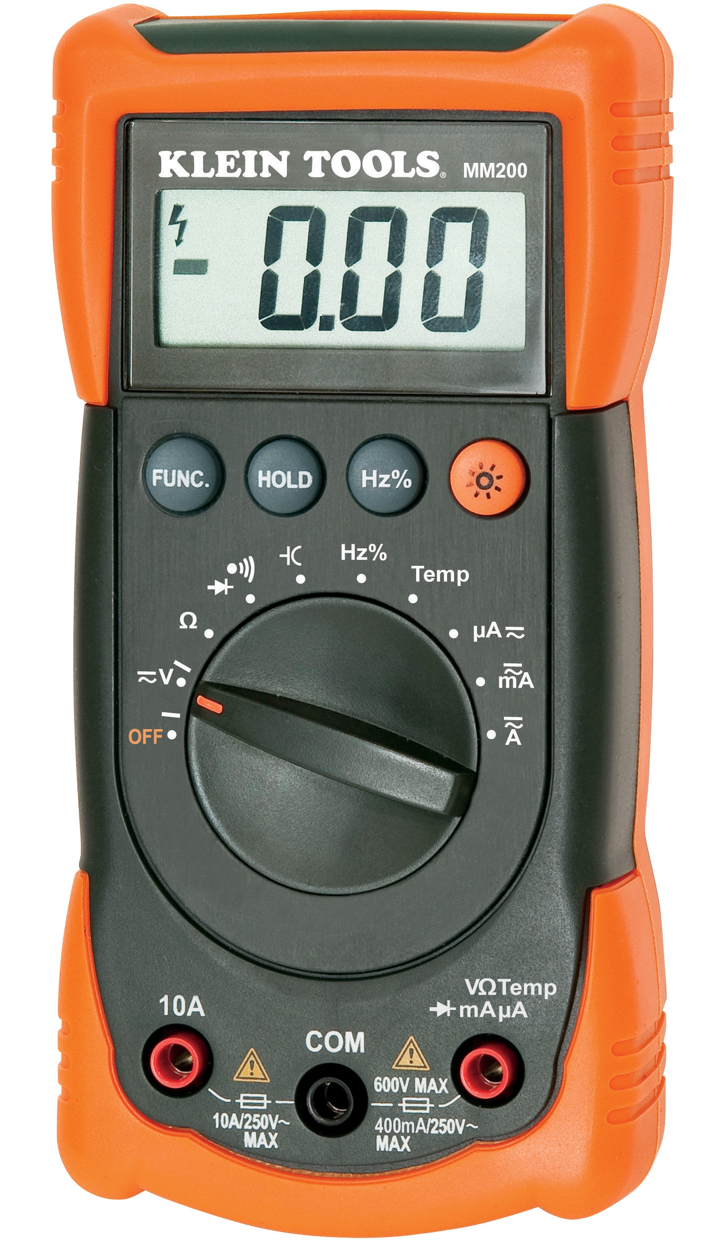
The CBM Automatic multimeter MM420 is essential for field electrical diagnostics—testing sensor outputs, verifying power supply integrity, and measuring control signal voltage. When multimeters produce incorrect readings, troubleshooting becomes impossible, leading to misdiagnosis of other equipment failures.
Typical Multimeter Failure Scenarios
Reading Drift: The multimeter displays values that don't match known reference voltages. On a 24V DC industrial power supply, readings might show 23.5V one moment and 26V the next, or consistently read 2-3V higher than actual values. This causes:
- False diagnosis of sensor faults (when the sensor is actually fine but the meter is inaccurate)
- Rejection of equipment that meets specifications
- Cascading confusion in troubleshooting chains
- Selector switch contact degradation
- Internal circuit board corrosion or cold solder joints
- Damaged input protection diodes
- LCD ribbon cable separation
- Backlight LED failure
- Contrast adjustment has drifted beyond usable range
Diagnostic Procedures
Step 1: Reference Voltage Testing
Use a known stable voltage source—the 24V DC power supply in most industrial control panels—as your reference. Set the multimeter to DC voltage mode and measure the supply. If the reading differs from the known 24V by more than ±0.5V, the meter requires calibration or replacement. Repeat this test with multiple known sources (12V, 48V if available) to determine if the error is systematic across ranges or isolated to specific voltage ranges.
Step 2: Function Mode Testing
Systematically test each measurement mode: DC voltage, AC voltage, resistance (ohms), and current if the meter supports it. For each mode, use appropriate reference sources:
- Use a 9V battery for DC voltage
- Use a known AC outlet (120V or 240V depending on region) for AC voltage
- Use precision resistors (marked 10Ω, 100Ω, 1kΩ) for resistance testing
- Use a small load circuit (LED with series resistor) for current measurement
If any mode fails to register or shows erratic readings, that specific circuit has failed.
Step 3: Input Probe Assessment
Damaged probes cause false readings as much as damaged meters. Test by connecting the red and black probes together—resistance should read near zero (0.1-0.5Ω depending on probe quality). If resistance shows as infinite or fluctuates, probe replacement is necessary. Inspect probe insulation for cracks allowing moisture contact with internal conductors.
Step 4: Battery and Power System Check
For battery-powered multimeters, use the meter's built-in battery test function if available. Display brightness issues in LCD screens often correlate with low battery voltage—the display circuits operate near the edge of their supply voltage range. Rechargeable batteries should be fully charged before testing; capacity loss preventing the meter from maintaining adequate voltage during use indicates battery replacement is needed.
Calibration vs. Replacement Economics
Multimeter calibration requires specialized equipment and expertise, typically costing 30-50% of a new meter's price. For a MM420 unit, if diagnostics reveal systematic measurement drift or multiple failed functions, procurement teams should budget for replacement rather than repair. However, if only the display is dim (usually correctable via contrast adjustment) or probes are damaged (easily replaced), repair extends equipment life cost-effectively.
Establishing a Measurement & Detection Preventive Maintenance Program
Best Practices for Procurement Teams
Based on 35+ years of industrial equipment distribution experience, 3G Electric recommends procurement engineers implement these practices to minimize Measurement & Detection failures:
Inventory Management: Stock spare thermometers in common ranges (0-50°C, -40 to +40°C) and backup inflator batteries. Downtime costs far exceed the expense of spare equipment.
Environmental Control: Store measurement instruments in climate-controlled areas separate from production floor vibration and moisture. Temperature sensors and electronic multimeters degrade faster when exposed to humidity, dust, and thermal cycling.
Regular Calibration: Establish quarterly calibration intervals for thermometers and annual certification for multimeters. Use certified reference standards and documented procedures.
Usage Documentation: Maintain logs of equipment usage, storage conditions, and any anomalies observed. This data identifies failure patterns and helps predict when replacement is due.
Supplier Partnerships: Work with distributors like 3G Electric who can provide technical support, warranty validation, and access to replacement components quickly. Our global supply chain ensures procurement teams receive equipment when needed, not weeks later.
Training: Ensure maintenance and engineering staff understand proper use of measurement equipment. Incorrect probe placement on thermometers or overloading multimeter inputs causes failures attributed to equipment defects rather than operator error.
Conclusion
Measurement & Detection equipment failures significantly impact industrial operations, but most issues are preventable or easily resolved with systematic troubleshooting. By understanding the specific failure modes of thermometers, expansion tank inflators, and electrical multimeters, procurement engineers can make faster decisions about repair versus replacement, reduce downtime, and maintain the measurement accuracy essential to industrial quality and safety.
When replacement is necessary, 3G Electric's 35+ years of experience sourcing reliable industrial measurement equipment ensures your team has access to proven products like the CBM thermometer series and MM420 multimeters. Contact our procurement specialists to discuss your facility's Measurement & Detection needs and establish preventive maintenance protocols suited to your operations.