Industrial Pumps & Compressors Troubleshooting Guide: Diagnosing Common Failures in Singapore Operations
Industrial pumps and compressors form the backbone of manufacturing, hydraulic, and fluid-transfer systems across Singapore. When these critical components fail, production halts and maintenance costs spiral. This comprehensive troubleshooting guide equips maintenance teams and service engineers with systematic diagnostic techniques to identify root causes, implement rapid repairs, and prevent recurrence. Whether you're managing compact gear pumps or high-displacement industrial systems, understanding failure signatures and diagnostic workflows separates emergency calls from planned maintenance.
Core Troubleshooting Framework for Pumps & Compressors
Effective troubleshooting begins with a structured diagnostic approach. Industrial pumps and compressors operate across four primary performance zones: pressure delivery, flow rate, temperature stability, and mechanical integrity. When failures occur, symptoms typically manifest across multiple zones simultaneously—a pressure drop may accompany elevated temperature and audible noise, yet each symptom points to different root causes.
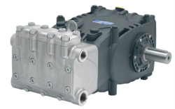
The first diagnostic step is establishing baseline performance data. Record nameplate specifications including design pressure (bar or MPa), rated flow (L/min), motor power (kW/hp), and rotation speed (rpm). Compare operational parameters against these baselines using portable pressure gauges, flow meters, and thermal imaging equipment. A Pratissoli KF30 pump rated at 200 bar and 106 L/min, for example, should maintain these parameters within ±5% under steady-state operation. Deviations beyond tolerance indicate component degradation or system configuration errors.
Next, isolate the fault location through systematic elimination. Separate pump performance issues from downstream system problems by installing isolation valves and measurement points. Use the pump displacement formula (Flow = Displacement × RPM / 1000) to calculate expected output and compare against measured flow. If measured flow falls below 90% of theoretical flow, internal leakage within the pump suggests seal or bearing wear. If flow matches theory but pressure remains low, the issue resides in downstream components—relief valve misadjustment, clogged filters, or pipe blockages.
Pressure signature analysis reveals failure mode patterns. Steady pressure loss indicates progressive wear. Sudden pressure spikes suggest relief valve malfunction or system shock. Oscillating pressure readings (±10–20 bar fluctuation) point to cavitation, aeration, or pump inlet starvation. Document pressure trends over time and correlate with operational events—motor speed changes, load variations, or ambient temperature shifts—to establish cause-and-effect relationships.
Diagnostic Procedures for Specific Pump and Compressor Failures
Low Pressure Output Despite Rated Motor Speed
This is the most common complaint across industrial sites. Begin by verifying motor speed using a non-contact tachometer. If motor speed meets specification (e.g., 1450 rpm for a Pratissoli SS7045 pump) but discharge pressure remains 30% below rated 200 bar, suspect internal leakage. Internal leakage in positive-displacement pumps occurs through worn clearances in the pump head, slipper bearings, or thrust plates. Perform a "load-holding" test: isolate the pump discharge, close the relief valve, run the pump at rated speed for 60 seconds, then measure pressure. Rapid pressure decay (more than 10 bar drop per minute) confirms internal leakage. Seal kit replacement or pump remanufacturing is typically required.
If motor speed is below specification, the root cause shifts to the motor or drive train. Check motor voltage and phase continuity. Verify coupling alignment and bearing condition. A misaligned coupling introduces radial load on pump input shafts, causing friction losses that appear as pressure deficits. Use laser alignment tools to confirm shaft concentricity to within 0.05 mm total indicated runout (TIR).
Excessive Temperature Rise and Reduced Flow
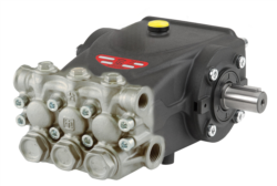
Temperature rise above 60°C in pump discharge fluid indicates energy dissipation as heat, typically from high internal leakage combined with external backpressure. The Interpump E1D1808 gear pump operating at design 180 bar should maintain fluid temperature below 50°C in steady-state conditions. When discharge fluid approaches 70°C, viscosity drops and internal clearances increase, creating a positive feedback loop: increased leakage generates more heat, which reduces viscosity further, allowing more leakage.
Measure pump case drain flow (return line to reservoir). A pump rated 8 L/min should return less than 1 L/min through the case drain under normal operation. Drain flow exceeding 20% of rated displacement indicates seal degradation. Common culprits include damaged thrust plate springs, worn swashplate guides in variable-displacement pumps, or failed mechanical seals. Thermal imaging of pump housing reveals hot spots at seal faces or bearing journals—focus maintenance efforts on these locations.
Check fluid viscosity using a portable viscosity meter. Oils oxidize and viscosity drops over time, particularly in tropical Singapore climates. Fluid with viscosity below 90% of original specification should be replaced. Low viscosity increases internal leakage and reduces film strength at bearing interfaces, accelerating wear.
Audible Noise: Cavitation vs. Mechanical Wear
High-frequency chattering or crackling noise at pump inlet signals cavitation—vapor bubble formation in low-pressure zones collapsing violently as pressure increases downstream. This acoustic signature differs from grinding noise (bearing wear) or knocking noise (bent shafts). Cavitation causes pitting damage to pump impellers and valve plates within hours, so immediate corrective action is critical.
Root causes of cavitation include: inlet line blockage (check suction filter pressure drop), excessively long inlet line (increase inlet line diameter), low fluid level in reservoir (maintain level 75% above minimum), or inlet temperature exceeding 50°C (poor ventilation). For a Pratissoli MW40 pump drawing 211 L/min, inlet line velocity should not exceed 1.2 m/s. Calculate velocity as V = (Flow in L/min ÷ 1000) / (Pipe Area in mm²/1000000). Undersized inlet lines create artificial inlet starvation.
Mechanical grinding noise emanates from bearing wear. Install vibration sensors (accelerometers) on pump casing and capture FFT (Fast Fourier Transform) spectrum data. Bearing wear produces broadband noise with peaks at bearing fault frequencies (typically 5–50 kHz range). Smooth rolling bearings show minimal energy in this range; worn bearings show elevated peaks. When bearing fault signatures exceed 4 g acceleration (RMS), bearing replacement is imminent.
External Leakage and Seal Failure
Oil weeping from shaft seals or pump head suggests mechanical seal wear or improper installation. New seals should show zero external leakage; acceptable leakage rates under ISO 4414 are typically less than 0.5 mL/min for standard applications. Observe seal area under UV light with fluorescent dye added to the working fluid—fluid traces indicate leakage paths.
Document leak location: shaft seal (rotating element), fixed-head joint, or case drain line. Each location indicates different failure modes. Shaft seal leakage usually reflects improper seal installation (misalignment, over-compression, or contamination during assembly). Fixed-head leakage suggests corrosion, thermal cycling stress, or fastener loosening. Case drain leakage points to back-pressure accumulation in the pump case—verify case drain line is unrestricted and returns to reservoir below fluid level.
Step-by-Step Diagnostic Workflow for Field Technicians
Phase 1: Data Collection (15 minutes)
1. Record ambient temperature, reservoir fluid level, and fluid color/odor (dark/burnt odor suggests overheating damage).
2. Measure discharge pressure at pump outlet using a calibrated glycerin-filled pressure gauge (0–250 bar range minimum).
3. Measure flow rate using an in-line turbine or electromagnetic flowmeter, or calculate from motor amperage and pump displacement if meter unavailable.
4. Record motor speed using a non-contact tachometer against pump coupling or motor shaft.
5. Measure pump case drain return flow using a graduated cylinder and stopwatch (collect return for 60 seconds, calculate L/min).
6. Capture infrared thermal images of pump housing, motor, and inlet/discharge lines—isothermal surfaces indicate stagnant zones or blockages.
Phase 2: Pressure Testing (10 minutes)
1. Close discharge isolation valve while pump operates at rated speed; observe pressure rise rate and final pressure. Rapid pressure rise (to rated pressure within 10 seconds) indicates good pump integrity; slow rise suggests internal leakage.
2. Open discharge valve incrementally and observe pressure-flow relationship. Plot pressure versus load (motor amperage) on graph paper or mobile device—nonlinear curves indicate pump slippage or relief valve drift.
3. Perform relief valve cracking pressure test: slowly increase load until relief valve opens, note cracking pressure against nameplate setting (typically ±5 bar tolerance acceptable).
Phase 3: Component Isolation (20 minutes)
1. If pressure is low but motor speed and flow are normal, isolate pump from downstream system using ball valves. Retest pressure with isolated pump—if pressure recovers to specification, the issue is in downstream components (filters, lines, valves). If pressure remains low, the pump is faulty.
2. If flow is low, measure pump case drain flow and compare to baseline—elevated drain flow confirms internal pump leakage; normal drain flow with low flow suggests motor underspeed or drive belt slippage.
Phase 4: Root Cause Assignment and Action Plan (15 minutes)
Based on diagnostic data, assign failure mode and prioritize corrective action. Document findings in maintenance log with photographs and measurements for trend analysis over system lifetime.
Selection Criteria and Best Practices for Pump Maintenance
Preventive maintenance extends pump service life by 200–300%. Implement these evidence-based practices:
Fluid Management
Change hydraulic fluid on schedule (annually for standard ISO 46 oils; 18 months for premium synthetic fluids in tropical climates). Singapore's high humidity and ambient temperatures (28–35°C year-round) accelerate fluid oxidation and water ingestion. Implement desiccant breathers on reservoir vents to exclude moisture while allowing air exchange. Test fluid samples quarterly for viscosity, acid number (TAN), and water content. Replace fluid immediately if water content exceeds 500 ppm or TAN exceeds 1.0 mg KOH/g.
Inlet Line Design
Properly sized inlet lines prevent cavitation. For a Pratissoli SS71153 pump delivering 122 L/min, size inlet line to achieve flow velocity of 0.6–0.9 m/s (target: 40 mm diameter hose minimum). Minimize inlet line length (target: less than 1 meter). Install 100-mesh suction filters and monitor pressure drop—differential exceeding 0.2 bar indicates filter clogging requiring cleaning.
Motor-Pump Alignment
Misalignment is invisible but costly. Check coupling runout every 500 operating hours using laser alignment equipment. Acceptable tolerance: 0.05 mm axial runout and 0.1 mm radial runout. Schedule recalibration whenever motor or pump is removed for service.
Vibration Monitoring
Establish vibration baseline on new pumps using portable FFT analyzers. Compare baseline against current readings monthly. Elevated broadband vibration (above 3 g RMS) signals bearing wear; spiky peaks at specific frequencies indicate blade-pass frequencies or cavitation. Trend rising vibration and schedule bearing replacement before catastrophic failure.
Compact Pump Applications
Smaller pumps like the Interpump E1D1808 (8 L/min at 180 bar, 5 kg) demand meticulous installation. Verify mounting base is rigid (deflection less than 0.5 mm under rated load) and motor coupling is precisely aligned. Case drain lines on compact gear pumps are sensitive to back-pressure—ensure case drain returns to tank unrestricted and below fluid level to prevent seal failure.
High-Flow Applications
Large-displacement pumps like the Pratissoli MW40 (211 L/min at 210 bar, 264 kg) generate significant heat and pressure pulses. Install primary and secondary relief valves (main and pilot reliefs) for stability. Use flexible hose connections at pump discharge to dampen pressure spikes and reduce stress on downstream piping. Monitor discharge line temperature continuously (target: 45–55°C)—temperature exceeding 60°C indicates overloading or internal leakage requiring immediate investigation.
Troubleshooting Decision Table
| Symptom | Primary Cause | Diagnostic Test | Corrective Action |
|---|---|---|---|
| Low pressure, normal flow, normal motor speed | Internal pump leakage or relief valve drift | Load-holding test: close discharge, observe pressure decay rate | If decay >10 bar/min: replace pump seals or remanufacture. If decay <5 bar/min: adjust relief valve cracking pressure. |
| Low flow, normal pressure, normal motor speed | Cavitation or inlet starvation | Check inlet line diameter, suction filter pressure drop, fluid level | Increase inlet line size, clean or replace suction filter, fill reservoir to 75% level minimum. |
| Low flow, low pressure, low motor speed | Motor underspeed or drive slippage | Verify motor voltage/phase, check coupling alignment and belt tension | Restore electrical supply, realign coupling, replace worn drive belt. |
| High temperature (70°C+), high case drain flow | Mechanical seal failure or swashplate wear | Measure case drain flow; infrared scan pump housing for hot spots | Replace pump seals, thrust plate, or remanufacture pump. Flush system to remove wear debris. |
| Cavitation noise (crackling), pressure instability | Inlet line blockage or inlet temperature high | Feel inlet hose (cold = blockage; hot = high inlet temp). Check suction filter pressure drop. | Clean/replace inlet filter, reduce inlet line length, improve reservoir ventilation, add cooler if inlet fluid >50°C. |
| Grinding noise, elevated vibration | Bearing wear or shaft damage | Capture vibration FFT spectrum; inspect shaft for visible damage | Replace pump bearings or entire pump if shaft is bent. Inspect drive coupling for damage. |
| External leakage at shaft seal | Mechanical seal wear or improper installation | Observe seal area under UV light with fluorescent dye tracer | Replace mechanical seal assembly; verify correct installation torque (typically 15–25 Nm for small pumps). |
This troubleshooting framework applies universally across pump families—from compact Interpump E1D1808 gear pumps to industrial-scale Pratissoli KF30 and Pratissoli MW40 systems. The diagnostic logic remains consistent: establish baselines, isolate failure location, assign root cause, and implement targeted corrective action.
Closing Recommendations and Next Steps
Systematic troubleshooting reduces emergency downtime and extends equipment service life. Maintenance teams equipped with portable diagnostic tools—pressure gauges, flow meters, thermal cameras, and vibration analyzers—can resolve 70% of field failures within one shift, eliminating costly pump exchanges.
For Singapore operations managing diverse pump portfolios, establish a centralized diagnostic protocol and train technicians on site-specific equipment configurations. Document baseline performance data when equipment is new, trending this data over years to predict failures weeks in advance. When failures do occur, your diagnostic logs provide invaluable context for root cause analysis and warranty claim substantiation.
3G Electric stocks a comprehensive range of industrial pumps and compressors from Pratissoli, Interpump, and leading manufacturers. Whether you require compact gear pumps for space-constrained applications or high-displacement units for large-scale hydraulic systems, our technical team can recommend equipment matched to your system specifications. We also provide technical documentation, spare parts, and preventive maintenance scheduling support. Contact 3G Electric today to discuss your pump system requirements and establish a preventive maintenance program that minimizes downtime and maximizes operational efficiency across your Singapore facility.