Understanding Pump System Failures and Maintenance & Service Requirements
Industrial pump systems are the backbone of high-pressure fluid operations, from hydraulic systems to spray application equipment. With over 35 years of experience as a distributor of industrial equipment, 3G Electric has observed that pump failures typically account for 40-60% of unscheduled maintenance events in manufacturing facilities. The primary challenge is that pump degradation often occurs gradually, making early detection difficult without systematic Maintenance & Service protocols.
Pump failures manifest in three primary failure modes: mechanical degradation (seal wear, bearing fatigue), performance loss (reduced flow, pressure decline), and catastrophic failure (cavitation, locked rotor). Understanding which failure mode is occurring is essential for determining whether repairs can restore functionality or replacement is necessary. This guide provides industrial professionals with actionable diagnostic techniques and preventive Maintenance & Service procedures that align with industry best practices.
The cost of unplanned pump replacement typically ranges from $5,000-$50,000 depending on pump type and system complexity. However, structured Maintenance & Service programs reduce unexpected failures by 70-85% when implemented correctly. This includes regular performance baselines, fluid analysis, vibration monitoring, and component inspection schedules.
Diagnostic Protocols: Identifying Pump Performance Degradation
Establishing Performance Baselines
Before troubleshooting can be effective, you must establish baseline performance metrics for your pump system. Record these parameters during normal operation:
- Flow rate (L/min): Measure outlet flow and compare against manufacturer specifications
- Operating pressure (bar): Monitor both system pressure and relief valve setting
- Power consumption (kW): Track electrical input to detect efficiency loss
- Vibration levels (mm/s): Use accelerometers to measure bearing wear indicators
- Fluid temperature (°C): Monitor inlet and outlet temperatures for thermal stress
- Acoustic signature (dB): Note baseline noise levels for comparison
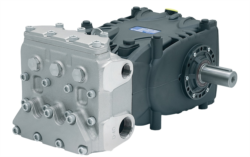
For high-performance pumps like the Pratissoli KF30 (106 L/min, 200 bar, 40 kW), baseline documentation is critical. If flow rates drop below 95 L/min or pressure exceeds 220 bar under normal load, degradation is occurring.
Pressure Drop Analysis
Excessive pressure drop indicates internal leakage or restriction. Measure pressure at three points:
1. Pump inlet: Should be near atmospheric (0-0.5 bar above ambient)
2. Pump outlet: Varies by system, typically 50-200 bar
3. System relief valve: Protects against overpressure
If outlet pressure drops more than 10-15 bar under constant load, suspect internal seal wear. This is particularly critical when operating higher-capacity units like the Pratissoli MW40 (211 L/min, 210 bar, 85 kW), where pressure loss indicates significant internal leakage.
Common causes of abnormal pressure drop:
- Damaged pump impeller or rotor
- Worn inlet or outlet port plates
- Seal degradation or failure
- Debris accumulation in relief valve
Flow Rate Verification
Flow reduction is one of the earliest indicators of pump wear. Use calibrated flow meters to measure:
- Actual outlet flow vs. nameplate specifications
- Flow consistency over a 10-minute operational window
- Flow response when load increases
A healthy pump maintains ±5% flow variance under constant conditions. If variance exceeds 10%, internal degradation is advancing. For compact systems like the Interpump PUMP E1D1808 L (8 L/min at 180 bar), even 1-2 L/min reduction signals wear requiring attention.
Component-Specific Maintenance & Service Troubleshooting
Seal and Bearing System Inspection
Pump seals and bearings fail through three mechanisms: mechanical wear (friction), thermal stress, and contamination. Implement these Maintenance & Service checks:
Visual Inspection Protocol:
- Check for external leakage around shaft seal area
- Examine bearing housing for heat discoloration (should not exceed 70°C)
- Look for debris or carbon buildup on visible surfaces
- Verify coupling alignment (misalignment causes accelerated bearing wear)
- Sample hydraulic fluid monthly from the system
- Analyze for water content (should be <500 ppm)
- Test viscosity—deviation >10% from specification indicates thermal degradation
- Perform particle count (ISO 4406 standard)—target is 17/15/12 or cleaner
Contaminated fluid is responsible for 80% of seal failures. Implement quarterly filter changes and maintain system cleanliness as foundational Maintenance & Service practice.
Pressure Regulator Integration and Monitoring
Pressure regulators like the Francel B25/37mb maintain stable outlet pressure despite inlet fluctuations. When integrated into pump systems, regulators require dedicated attention:
Regulator Performance Verification:
- Measure outlet pressure stability ±1 mbar deviation over 60 seconds
- Verify response time when inlet pressure changes (should respond within 500ms)
- Check relief valve cracking pressure (should match specification ±0.5 bar)
- Ensure vent size (10mm on B25/37mb) is unobstructed
- Chatter or oscillation: Indicates internal spring degradation or worn poppet surfaces
- No pressure rise: Blockage in inlet or damaged internal poppet
- Pressure overshoot: Relief valve pilot pressure loss or stuck poppet
- Fluid leakage: Worn seat surfaces or damaged seals
If regulator malfunctions are suspected, isolate it from the pump circuit and test independently. Many apparent pump failures are actually regulator problems preventing proper system operation.
Nozzle and Spray System Maintenance & Service
When pumps feed spray or injection systems, nozzle performance directly reflects pump health. Equipment like the Euspray flat jet nozzle (25° angle, HP 1/4" BSPT) depend on consistent pressure and flow:
Spray Pattern Analysis:
- Document spray pattern during normal operation (reference photos helpful)
- Monitor pattern changes—asymmetry indicates inlet port wear
- Check droplet size consistency—enlargement suggests pressure loss
- Verify spray angle (25° specified for this nozzle model)
- Partial blockage causes uneven spray patterns
- Test by temporarily replacing nozzle with identical unit
- If spray normalizes, original nozzle requires cleaning or replacement
- Use ultrasonic cleaning for mineral deposits; never use chemical solvents that damage elastomers
Nozzle deterioration often precedes pump performance loss, making spray analysis an early warning system for Maintenance & Service planning.
Preventive Maintenance & Service Schedules and Operational Protocols
Condition-Based Maintenance (CBM) Framework
Moving beyond fixed-interval schedules, condition-based Maintenance & Service monitors actual equipment state:
Weekly Monitoring:
- Visual inspection for leaks or unusual discoloration
- Pressure and flow verification against baseline
- Acoustic assessment (unusual grinding, whining, or cavitation sounds)
- Fluid temperature monitoring (alert if exceeding 60°C)
- Fluid sample analysis for contamination and viscosity
- Vibration measurement at bearing housings and pump base
- Pressure gauge calibration verification
- Coupling and mounting bolt inspection
- Hydraulic filter replacement (or cleaning if system design permits)
- Seal inspection and lubrication verification
- Relief valve functional test
- Complete system pressure and flow mapping
- Professional vibration analysis and trend comparison
- Thermal imaging of bearing housings and seals
- Pump efficiency calculation (actual power vs. theoretical requirement)
- Seal replacement if showing wear (preventive replacement extends system life 2-3 years)
Operational Best Practices
How equipment is operated directly impacts Maintenance & Service frequency and cost:
Flow and Pressure Management:
- Operate within 80-95% of nameplate capacity when possible
- Avoid continuous operation at maximum pressure—most systems need only 70-80% of relief setting
- Allow 15-minute warm-up period before full-load operation
- Enable 5-minute cool-down cycles during extended operation
- Maintain inlet fluid temperature between 40-50°C for optimal pump life
- Install coolers if operation routinely exceeds 55°C
- Check cooler performance monthly—scale buildup reduces efficiency 15-30% annually
- Change hydraulic fluid every 5,000 operating hours (not calendar-based)
- Use manufacturer-specified fluid type (viscosity and additive package matter significantly)
- Implement offline filtration if contamination is recurring problem
- Maintain system cleanliness to ISO 17/15/12 or better
- When using multiple components like MW40 pumps with Francel regulators and Euspray nozzles, test integration during initial commissioning
- Document pressure and flow at each component connection point
- Verify compatibility of all fluid paths to prevent incompatible fluid mixing
- Establish isolation procedures for component-level testing
Emergency Troubleshooting and Failure Response
Rapid Diagnostics for Operational Failures
When pump systems fail unexpectedly, time-critical diagnostics determine response strategy:
Step 1: Safety Verification (First 30 seconds)
- Isolate power and relieve system pressure
- Check for leaking hot fluid (burn hazard)
- Ensure personnel safety before proceeding
- Measure current system pressure and flow
- Listen for unusual sounds (grinding, cavitation, squealing)
- Observe fluid condition (color, clarity, odor)
- Document all observable symptoms
- If possible, test pump independent of system (bench test)
- Verify pressure regulator operation separately
- Check if system operates with alternative pump or regulator
- Determine if failure is component-level or system-integration issue
- No flow/no pressure: Likely inlet blockage, pump cavitation, or seized rotor
- Low pressure only: Suspect internal leakage, worn seals, or regulator malfunction
- Low flow only: Indicates regulator or relief valve over-restriction
- Erratic pressure/flow: Points to seal degradation or contamination in fluid
- Severe noise + pressure loss: Usually indicates bearing failure requiring immediate replacement
Temporary Operations and Extended Service Life
When replacement is not immediately available, temporary measures can extend equipment operation:
- Reduce system pressure: Operating at 70% of normal extends pump life 2-3 months
- Limit flow demand: Restrict load to minimum required for operations
- Increase monitoring: Check pressure and flow every 2 hours
- Enhance cooling: Install temporary coolers to reduce thermal stress
- Expedite replacement: Order replacement unit immediately—temporary operation risks catastrophic failure
Never operate equipment known to have seal failures or bearing wear beyond 2 weeks without replacement planning. Catastrophic failure creates secondary damage costing 3-5x the original repair cost.
Documentation and Maintenance & Service Record Management
Systematic documentation transforms reactive maintenance into predictive capability. Maintain permanent records including:
- Installation specifications: Pump model, serial number, installation date, initial baseline readings
- Operational history: Hours of operation, pressure settings, flow demands, temperature extremes
- Service events: All repairs, seal replacements, fluid changes with dates and technician notes
- Performance trends: Pressure, flow, vibration, and temperature data at regular intervals
- Spare parts inventory: Critical components on-hand for rapid replacement (seals, bearings, shaft elements)
After 35 years as an industrial equipment distributor, 3G Electric observes that facilities with rigorous Maintenance & Service documentation experience 40% fewer emergency failures and 25% lower total maintenance costs annually. Digital systems and cloud-based platforms now enable real-time monitoring and predictive analytics previously impossible with paper records.
Implementing this comprehensive Maintenance & Service approach requires initial investment in training, equipment, and systems. However, the return through extended equipment life, reduced downtime, and improved reliability typically delivers ROI within 12-18 months for facilities operating multiple high-value pump systems.