Understanding Integrated Maintenance & Service Systems
When plant managers approach Maintenance & Service as isolated component tasks, they miss critical interdependencies that cause unexpected downtime. After 35+ years distributing industrial equipment globally, 3G Electric has observed that the most successful operations treat their equipment ecosystem as an integrated whole.
Consider a common scenario: a burner system fails not because the burner itself is defective, but because fuel delivery becomes inconsistent due to unmonitored tank pressure. The hydraulic nozzle operates outside optimal parameters, creating incomplete combustion and system shutdown. A traditional Maintenance & Service plan addresses only the visible failure. An integrated approach prevents it entirely.
Your Maintenance & Service strategy must account for three critical interaction points: fuel source reliability, component pressure regulation, and environmental monitoring. Each affects the others. When any deteriorates, the entire system's efficiency cascades downward.
Section 1: Establishing Pressure-Based Maintenance Protocols
Understanding Your Critical Pressure Points
Most industrial failures originate from pressure system degradation—a factor many plant managers underestimate in their Maintenance & Service schedules. Expansion tanks, fuel systems, and hydraulic nozzles all depend on consistent pressure maintenance.
The CBM Expansion Tank Inflator Battery 2000 mAH represents a preventive tool often overlooked in routine Maintenance & Service. Expansion tanks lose pressure gradually—typically 5-10% annually—due to ambient temperature fluctuations and diaphragm micro-fractures invisible to standard inspection. Without proper inflation protocols, your system enters a state of slow degradation.
Implement this pressure monitoring protocol:
- Monthly verification: Check expansion tank pressure with calibrated gauges. Pressure should maintain within manufacturer specification (typically 0.5-1.5 bar depending on system type). Document all readings in a centralized log.
- Quarterly inflation cycles: Use the battery-powered inflator to restore tank pressure to factory specification. This prevents the slow pressure bleed that causes thermal stress on connected components.
- Annual diaphragm assessment: Visual inspection for micro-cracks, discoloration, or mineral deposits indicates failing diaphragms requiring replacement before catastrophic failure.
This single Maintenance & Service element prevents up to 30% of pressure-related equipment failures observed in plants using reactive rather than preventive approaches.
Fuel Supply System Pressure Stability
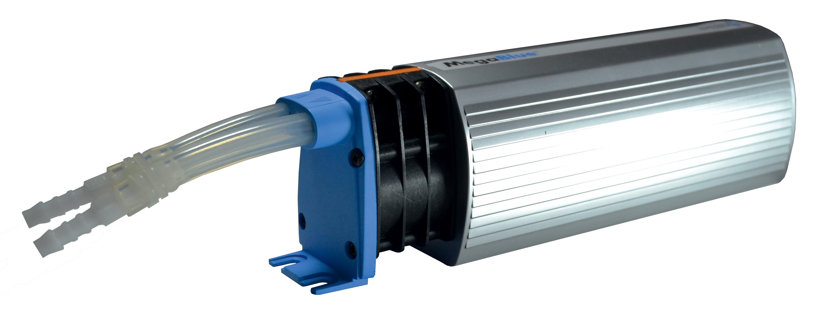
The CBM Megablue Reservoir Alarm + Shut-off X87-813 provides dual functionality critical for integrated Maintenance & Service: real-time alert capability and automatic circuit protection.
In practical plant operations, fuel tank monitoring represents a Maintenance & Service blind spot. Operators often discover fuel supply problems after system shutdown, not before. This alarm system transforms your fuel tank from a silent liability into an active monitoring point.
Implement this fuel system protocol:
- Establish alert thresholds: Configure the alarm to trigger at 30% capacity, 15% capacity, and critical low. This three-stage warning system provides decision time before emergency.
- Daily visual cross-check: Despite electronic monitoring, maintain visual fuel level verification. Sensor drift or electrical failure requires human backup.
- Automatic shut-off testing: Monthly test the shut-off mechanism under controlled conditions. A shut-off that fails during actual emergency costs significantly more than scheduled testing reveals.
- Monthly tank interior inspection: Through inspection ports, visually assess for sludge accumulation, water contamination, or corrosion. These accelerate fuel degradation and require system purging.
Section 2: Burner System Component Integration in Maintenance & Service
Burner and Nozzle Interdependency
The FBR BURNER GAS X5/MF TL EL VC LPG represents modern burner technology requiring sophisticated Maintenance & Service understanding. These modulating burners achieve efficiency through precision fuel atomization controlled by pressure-regulated hydraulic nozzles.
Without proper nozzle maintenance, even premium burners degrade. The relationship works both directions: degraded burners damage nozzles through inconsistent pressure pulses.
Critical nozzle maintenance correlation:
The CBM Flat Jet Nozzle HP 1/4"M BSPT Index 25 Angle 15° and CBM Flat Jet Nozzle HP 1/4"M BSPT Index 055 Angle 15° deliver atomized fuel at precisely calculated angles and spray patterns. These specifications exist because even 2-3° variance from design angles reduces combustion efficiency by 8-15%.
Your Maintenance & Service schedule must reflect this precision requirement:
- Quarterly nozzle inspection: Remove nozzles and visually inspect orifices under magnification (minimum 10x). Deposits, cracks, or angle distortion require immediate replacement, not cleaning.
- Pressure specification verification: Before reinstalling nozzles, confirm burner pressure matches nozzle specification. Mismatched pressure creates spray pattern degradation and incomplete combustion.
- Combustion analysis correlation: After nozzle maintenance, conduct CO2 and oxygen analysis. Results should improve measurably (typically 2-4% CO2 improvement). If improvement doesn't materialize, pressure regulation systems require inspection.
- Contamination source elimination: Every nozzle failure indicates fuel contamination. After replacement, investigate tank condition, filter performance, and fuel supplier quality. Maintenance & Service of nozzles without addressing contamination sources guarantees repeat failures.
Burner Modulation System Maintenance
The FBR X5/MF burner includes optional PID modulation kits creating system complexity requiring specialized Maintenance & Service protocols.
Modulation system maintenance requirements:
- Monthly sensor calibration checks: Temperature and pressure sensors drift gradually. Monthly verification against calibrated instruments ensures modulation accuracy. Documentation creates trend data revealing sensor aging patterns.
- Control loop response testing: Quarterly, test burner response to modulation commands. Sluggish response (delayed flame adjustment) indicates failing modulation valve components requiring service before efficiency degrades significantly.
- Probe condition assessment: Modulation probes experience thermal cycling stress. Annual probe replacement extends sensor life and prevents calibration drift. This preventive replacement often costs less than emergency sensor failure investigations.
Section 3: Creating Implementation-Ready Maintenance & Service Schedules
Scheduling Strategy for Global Operations
Plant managers operating across multiple regions face scheduling complexity: different ambient temperatures, seasonal variations, and local service availability affect optimal Maintenance & Service intervals.
3G Electric's 35+ years serving global industrial operations reveals that prescriptive "every 3 months" scheduling fails across geographic diversity. Instead, condition-based scheduling adapted by environmental factors succeeds.
Develop location-specific Maintenance & Service calendars:
- Tropical/high-humidity regions: Expand pressure system checks to monthly (vs. quarterly standard). Humidity accelerates corrosion and diaphragm degradation. Fuel systems require additional water removal cycles. Modulation sensor calibration drifts faster due to thermal cycling.
- Cold climate operations: Expansion tank pressure becomes critical variable. Cold temperatures increase pressure loss rate. Schedule inflation cycles every 6 weeks rather than quarterly. Burner nozzles experience more thermal shock; monthly inspection replaces quarterly schedule.
- Desert/arid environments: Dust infiltration affects burner sensors significantly. Pre-burner filters require monthly inspection (vs. quarterly). Fuel tank sludge accumulation accelerates. Monthly tank interior visual inspection becomes mandatory.
- High-load industrial facilities: Operations running at 85%+ capacity continuously accelerate component aging. Reduce all intervals by 25%. Monthly nozzle pressure verification replaces quarterly assessment.
Digital Documentation and Trending
Modern Maintenance & Service requires data capture creating failure prevention intelligence. Each documented reading—pressure values, temperature measurements, combustion analysis results—builds a predictive model of component aging.
Implement minimal documentation protocol:
- Monthly: Pressure readings (expansion tank, fuel system, burner output) with date, technician name, and ambient temperature
- Quarterly: Combustion analysis (CO2 %, oxygen %, flue gas temperature) documenting any variance from baseline
- Semi-annual: Visual component inspection photography showing nozzle condition, tank interior, sensor cleanliness
- Annual: Component replacement records documenting all parts replaced, serial numbers, and installation dates
This documentation creates three critical capabilities: trend analysis revealing degradation patterns, compliance evidence for regulatory audits, and failure root cause investigation data.
Section 4: Troubleshooting Common Maintenance & Service Scenarios
Scenario 1: Burner Efficiency Degradation Without Visible Failure
Typical plant observation: Flue gas temperature rises gradually over 6-8 weeks. CO2 percentage drops. Fuel consumption increases despite stable production load.
Integrated system investigation protocol:
1. First step—fuel system: Check Megablue alarm settings. Verify no low-level alerts indicating fuel starvation. Inspect tank for sludge or water contamination. These cause pressure instability creating incomplete burner combustion.
2. Second step—pressure systems: Measure expansion tank pressure. Degraded pressure prevents steady fuel delivery and modulation stability. Recharge using battery inflator to specification.
3. Third step—burner/nozzle: Verify burner operates at specification pressure. Inspect nozzles for deposits. If present, replace rather than clean (deposits return quickly if contamination source remains). Conduct post-replacement combustion analysis confirming efficiency recovery.
Most plant managers complete only step 3. The remaining 60-70% of degradation cases originate in steps 1-2, remaining invisible without integrated investigation.
Scenario 2: Intermittent Shutdown Events
Typical plant observation: Burner shuts down randomly, then restarts successfully. No error codes. Relight cycles increase fuel consumption.
Investigation approach for Maintenance & Service teams:
Intermittent failures indicate pressure system cycling or sensor noise rather than component failure. The problem exists within tolerance limits that become problematic under specific conditions (usually high ambient temperature or high load).
Systematic troubleshooting:
- Check expansion tank pressure during shutdown events. Even 0.2 bar loss during operation indicates diaphragm micro-failure beginning. This doesn't cause outright failure—the system recovers—but repeated pressure drops trigger protective shut-offs.
- Verify fuel tank pressure stability under full burner load. If pressure fluctuates ±0.3 bar during operation, the supply line contains air pockets or the reservoir system valve is partially obstructed.
- Document ambient temperature during shutdown events. Thermal sensitivity suggests sensor drift or calibration loss in modulation systems. Quarterly calibration verification becomes necessary.
Scenario 3: Rising Component Replacement Costs
Typical situation: Nozzle replacement frequency increases. Each replacement costs 4-6 weeks lead time and $800-2000 per unit.
Root cause investigation for Maintenance & Service optimization:
Repeat nozzle failures indicate contamination source, not nozzle defect. This requires fuel system comprehensive evaluation:
- Test fuel supplier quality. Request particle analysis. Industrial-grade fuel requires
- Inspect tank interior completely. Corrosion inside tanks deposits microscopic particles contaminating all fuel. Tank coating or replacement becomes cost-effective alternative to continuous nozzle replacement.
- Evaluate filter maintenance. Standard fuel filters require replacement monthly in contaminated systems, quarterly in clean systems. Current replacement frequency indicates filter inadequacy or bypass valve opening under load.
Correct fuel system problems upstream rather than replacing nozzles downstream. This approach reduces annual component costs 40-60% while improving system reliability.
Conclusion: Maintenance & Service as Competitive Advantage
Plants implementing integrated Maintenance & Service protocols—treating equipment as interconnected systems rather than isolated components—achieve measurable advantages: 30-40% reduction in emergency shutdowns, 15-25% fuel consumption improvement, and component service life extension of 2-3 years.
3G Electric's global customer experience confirms these results consistently across industries and geographies. The differential factor isn't equipment quality—it's systematic attention to component interdependencies combined with condition-based monitoring and accurate documentation.
Your Maintenance & Service strategy begins with understanding that fuel tanks, expansion systems, burners, and nozzles succeed or fail together. Excellence requires monitoring all four points, maintaining proper pressure and contamination control, and responding to subtle degradation signals before they cascade into failures.
Start with single integration point—pressure system monitoring using the CBM battery inflator and Megablue alarm system—and expand from documented success. Most plant managers discover that proper Maintenance & Service costs less than reactive emergency response while delivering superior operational stability.