Oil Supply System Maintenance & Service in Singapore: Complete Pump and Pressure Regulation Guide
Industrial oil supply systems demand rigorous maintenance protocols to ensure operational reliability and safety compliance in Singapore's demanding industrial environment. Whether operating fuel burners, hydraulic systems, or specialised industrial equipment, understanding how to properly service oil pumps, pressure regulators, and associated components is critical to preventing costly downtime and extending equipment lifespan. This comprehensive guide addresses the technical fundamentals of oil supply system maintenance, provides step-by-step service procedures, and highlights the diagnostic tools and replacement components essential for maintaining peak system performance in tropical industrial settings.
Understanding Oil Supply System Architecture and Maintenance Requirements
Modern industrial oil supply systems operate as integrated units comprising fuel delivery pumps, pressure regulation valves, solenoid-controlled flow mechanisms, and precision instrumentation. The system's primary function is to deliver fuel at precise pressures and flow rates to burners or other combustion equipment, with variations depending on whether the installation uses single-pipe or two-pipe supply configurations.
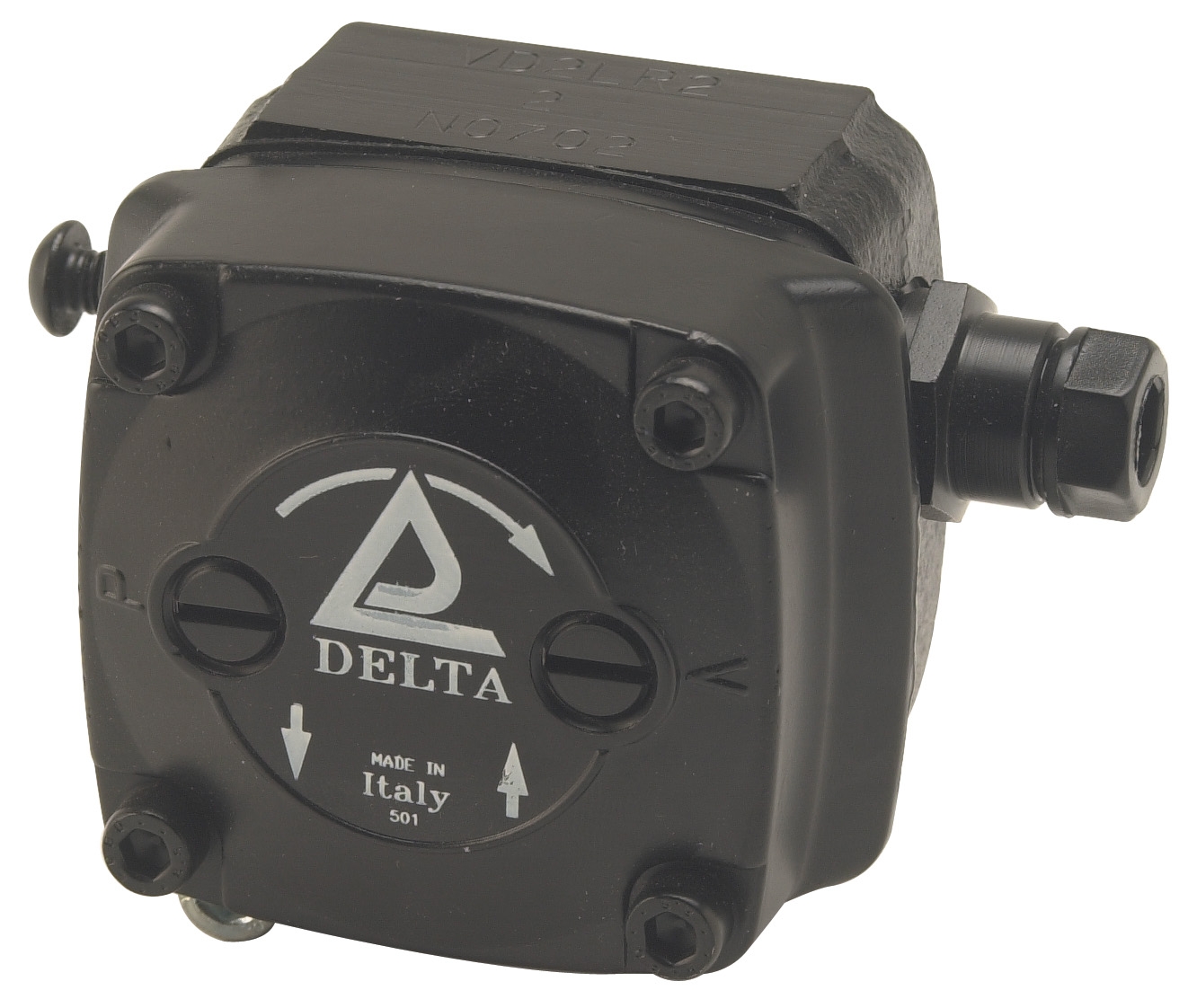
The CBM VD2 LR-2.2 low-pressure pump exemplifies modern fuel unit design, incorporating a self-priming mechanism with high suction capability—critical features for reliable operation in two-pipe systems common throughout Singapore industrial facilities. These compact units, manufactured to international EN 225 standards, feature mounting flanges compatible with standard oil burners, yet their reliability depends entirely on consistent maintenance discipline.
Maintenance requirements stem from several operational realities. Oil degrades over extended periods, developing sludge and varnish deposits that obstruct fuel flow and damage precision components. Pressure fluctuations stress seals and gaskets, leading to gradual degradation. Moisture contamination—particularly prevalent in Singapore's humid tropical climate—promotes corrosion of internal passages and valve seats. Particulate matter accumulates in filters and fuel lines, restricting flow and increasing component wear.
Preventive maintenance addresses these challenges through systematic inspection schedules, fluid analysis, filter replacement, and pressure verification protocols. The interval frequency depends on fuel quality, system age, and operational hours, but industry best practice recommends quarterly inspections for continuously-operated systems and biannual service for intermittent applications. Singapore-based operators must also account for environmental factors—coastal facilities face accelerated corrosion risks, while humid inland locations require enhanced moisture management protocols.
Technical Specifications and Component Interdependencies
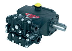
Effective oil supply system maintenance requires understanding how system components function as integrated units. The Interpump PUMP 5015 R ATEX delivers 15 L/min at 500 bar pressure with 20 hp (14.7 kW) power input, operating at 1450 rpm with overall dimensions of 351.5 x 242.5 x 195.5 mm and weighing 19.5 kg. These specifications define the pump's operating envelope and establish baseline performance metrics for diagnostic comparison during maintenance procedures.
Pressure regulation components work in partnership with delivery pumps. The CBM Coil 1930.1814 230V VML 2"1/2-3" 200mbar solenoid valve assembly controls high-capacity fuel flow in medium-pressure applications, while the CBM Coil 24V AC for ELV7 series handles proportional flow regulation in lower-pressure circuits. Both coil assemblies demand voltage verification during commissioning and periodic electrical continuity testing during service cycles.
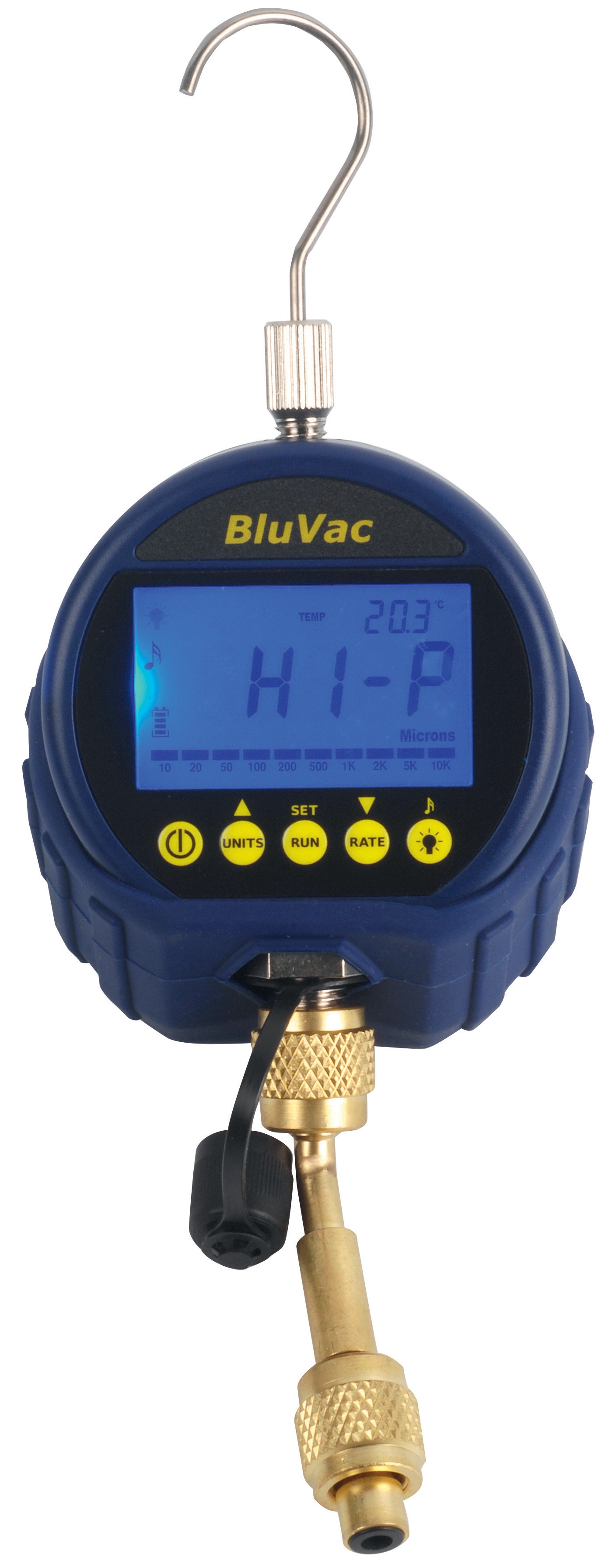
Instrumentation provides critical system visibility. The CBM Stainless Steel Axial Manometer D63 0/+400 Mbar offers ±1.6% accuracy across its 63 mm dial, suitable for low-pressure pneumatic and hydraulic applications with copper alloy wetted parts and stainless steel casing—essential specifications for long-term tropical reliability. The CBM Digital vacuum gauge BluVac complements pressure measurement with vacuum diagnostics, enabling technicians to identify suction-side leaks and pump cavitation risks that degrade performance before catastrophic failure occurs.
Integration between components demands attention during maintenance. Fuel system pressures must remain within equipment manufacturer specifications—typically 2.5-4 bar for two-pipe systems and 7-10 bar for single-pipe configurations. Pressure excursions beyond these windows indicate component degradation and warrant immediate investigation. Flow rates must match burner requirements; undersupply causes flame instability and incomplete combustion, while overpressure stresses seals and shortens component service life.
Step-by-Step Oil Supply System Maintenance Procedures
Step 1: Pre-Service Safety Verification
Isolate electrical power to the entire fuel system using lockout-tagout procedures. Verify system depressurisation by opening a test gauge port—pressure should drop to zero within 30 seconds. Allow system to cool for minimum 15 minutes before commencing work to prevent burn injuries from residual heat.
Step 2: Visual Component Inspection
Examine all fuel lines for visible cracks, corrosion, or signs of leakage. Check pipe connections and fittings for weeping—even minor seepage indicates seal degradation requiring replacement. Document any colour changes in visible fuel samples; dark brown or black discolouration indicates oxidation and contamination requiring fuel system flushing before resuming operation.
Step 3: Filter Element Replacement
Access fuel filter housings and measure differential pressure across the element using a calibrated manometer (such as the CBM ROS23014). If pressure differential exceeds manufacturer specifications—typically 0.5 bar for suction-side and 1.0 bar for discharge-side filters—replace the element. Dispose of used filters according to local environmental regulations; do not pour fuel residue into drains.
Step 4: Pressure System Diagnostics
Install calibrated pressure gauges at pump discharge and burner supply points. Record static pressures with the pump running at idle and under simulated load (achieved by partially restricting the return line). Compare readings against baseline specifications; pressure variations exceeding ±10% indicate pump wear or valve malfunction.
Step 5: Electrical Component Verification
Using a digital multimeter, verify coil resistance for solenoid valve assemblies (CBM ELK26121 and similar units). Typical solenoid resistance ranges 200-3000 ohms depending on design; open-circuit or short-circuit readings indicate coil failure requiring replacement. Verify supply voltage at solenoid terminals matches nameplate ratings (230V AC for CBM ELK26121; 24V AC for CBM ELV93006).
Step 6: System Repressurisation and Performance Testing
Gradually repressurise the system, observing gauge readings for anomalies. Run the system at operating temperature for minimum 30 minutes, recording pressure stability and cycle performance. Any unexplained pressure drift or instability warrants additional diagnostic investigation before returning equipment to service.
Component Selection and Maintenance Best Practices for Singapore Operations
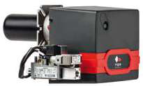
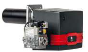
Selecting appropriate replacement components requires matching original equipment specifications precisely. The FBR X GAS XP 60 CE TC EVO metano burner (_41) operating between 232-630 kW maximum output demands fuel system components rated for sustained high-pressure delivery—the Interpump PUMP 5015 R ATEX with its 500 bar rating and 14.7 kW power provision represents appropriate system pairing for this burner class.
Singapore operators should prioritise components manufactured to European standards (EN 225 pump mounting, CE marking for electrical assemblies) and featuring corrosion-resistant materials—stainless steel cases for gauges, copper alloy or bronze for valve bodies. Avoid inferior replacement components; false economy on cheap substitutes typically results in accelerated failure and extended downtime exceeding the cost differential within 12-18 months.
Establish routine documentation practices: maintain fuel analysis records tracking viscosity, water content, and acid number trends; log pressure readings and cycle times for early-warning system degradation patterns; photograph component conditions during teardown to support failure analysis. This data enables predictive maintenance scheduling, preventing emergency repairs that disrupt production schedules.
Partner with experienced distributors offering technical support and genuine replacement components. Access to solenoid valve assemblies, industrial pumps, and pressure measurement instruments from established manufacturers ensures system reliability and facilitates troubleshooting support when technical questions arise during service procedures.
Closing Remarks and Professional Support Resources
Oil supply system maintenance protects your industrial investment, ensures operational safety, and sustains the performance reliability your business depends upon. The procedures outlined in this guide provide a technical framework for systematic maintenance, yet individual system configurations may demand site-specific adaptations. Environmental conditions unique to your facility location—coastal humidity, ambient temperature extremes, fuel quality variations—all influence maintenance interval frequency and component selection decisions.
At 3G Electric, we've supported Singapore industrial professionals since 1990, providing maintenance and service components including pumps, pressure regulators, solenoid valves, and diagnostic instrumentation from trusted manufacturers. Our technical team understands tropical industrial operating conditions and can recommend maintenance strategies tailored to your specific equipment and operational environment. Contact 3G Electric today to discuss your oil supply system maintenance requirements or to access genuine replacement components and diagnostic support for your facility's critical systems.