Introduction: Coordinated Maintenance for Complex Industrial Systems
Industrial facilities rarely operate in isolation. Your maintenance team likely manages interconnected systems where a pressure regulator feeds into a pump circuit, which then delivers fluid through precision nozzles to combustion or lubrication points. When these components operate independently, failures cascade unpredictably.
Maintenance & Service strategies that address individual components miss the bigger picture. A clogged nozzle doesn't just waste fuel—it signals upstream pressure problems. A pump losing flow may indicate regulator drift rather than pump wear.
Drawing on 35+ years of industrial equipment distribution experience, 3G Electric has observed that the most reliable facilities apply integrated maintenance protocols that treat systems holistically. This guide provides maintenance teams with actionable procedures to diagnose, service, and prevent failures across pressure regulation, high-flow pump systems, and fluid delivery nozzles.
Section 1: Pressure Regulator Inspection and Calibration Protocols
Understanding Your Regulator's Role
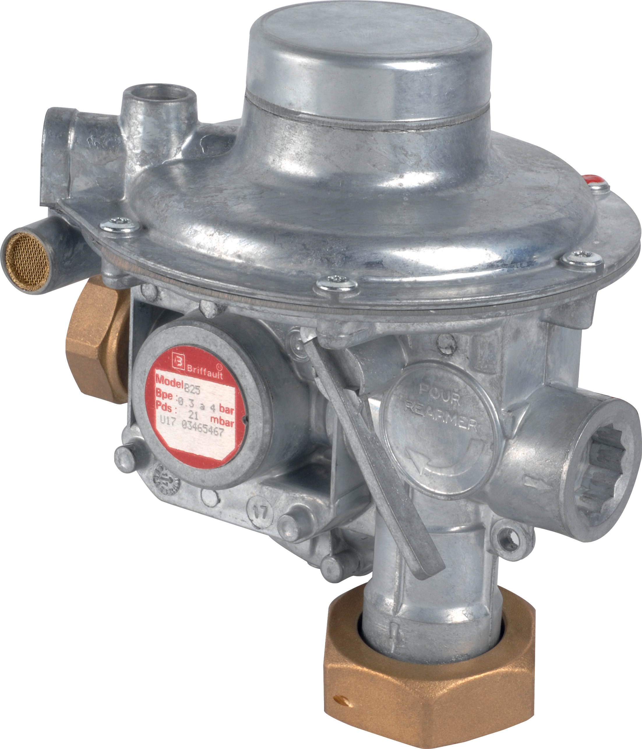
Pressure regulators like the Francel B25/37mb with safety relief do more than maintain outlet pressure—they protect downstream equipment from overpressure spikes and stabilize system performance. A drifting regulator creates a domino effect: inconsistent nozzle spray patterns, pump cavitation, and premature component failure.
Monthly Visual Inspection Checklist
Schedule regulator inspections monthly or after any system shutdown exceeding 48 hours:
- Vent and relief port examination: Check the 10 mm vent for blockages, corrosion, or mineral deposits. Use a soft brush and low-pressure air (never liquid) to clear debris.
- Outlet pressure gauge reading: Compare against your target setpoint. A drift of more than ±2 mbar indicates internal spring fatigue or diaphragm wear requiring replacement.
- Body integrity: Look for cracks, corrosion spots, or weeping at the diaphragm seal. Mark any discoloration for follow-up at the next service cycle.
- Connection fittings: Tighten any loose NPT or SAE connections by hand first, then apply a wrench with steady pressure (do not over-torque—63 Nm maximum for most industrial regulators).
- Relief valve response: If your system design permits safe testing, manually trigger the relief and confirm the outlet pressure drops within 0.5 seconds.
Recalibration and Spring Maintenance
Regulator springs lose tension over time, especially in facilities with temperature swings exceeding 20°C daily. Recalibrate your setpoint quarterly:
1. Connect a certified test gauge (±1% accuracy minimum) to the regulator outlet.
2. Adjust the setpoint screw counterclockwise by one-quarter turn increments until your target pressure is reached.
3. Document the adjustment in your maintenance log with date, technician name, and before/after readings.
4. If you must turn the screw more than two full rotations to reach target pressure, order a replacement regulator—the internal spring is nearing end-of-life.
When to Replace vs. Recalibrate
Regulator replacement becomes necessary when:
- Vent ports remain blocked after cleaning (indicates internal seal degradation)
- Outlet pressure fluctuates ±5 mbar or more under steady-state load
- Relief valve responds slower than 1 second to overpressure
- Any visible cracks appear in the body or diaphragm housing
Section 2: High-Performance Pump Service and Flow Rate Verification
Pump Selection and Performance Baselines
Industrial facilities typically operate pumps in two categories: mid-range units like the Pratissoli KF30 (106 L/min, 200 bar, 40 kW) for general circulation, and high-capacity systems like the Pratissoli MW40 (211 L/min, 210 bar, 85 kW) for heavy-duty applications. Establishing accurate performance baselines is essential before degradation occurs.
Initial Commissioning Documentation
When a new pump enters service, capture these measurements within the first 8 operating hours:
- Inlet and outlet pressure: Record with calibrated gauges at 25%, 50%, 75%, and 100% load settings.
- Flow rate: Use an inline flowmeter or time-based collection method (fill a calibrated container and divide by seconds elapsed).
- Bearing temperature: Measure with an infrared thermometer at the pump body center. Typical baseline: 35–45°C above ambient.
- Acoustic signature: Describe any whining, grinding, or cavitation noise (none should be present).
- Motor current draw: If the pump runs on an electric motor, record input amperage at each load point.
Store these baselines in a physical binder and digital database—they become your diagnostic reference for the pump's entire operational life.
Quarterly Flow Rate Testing
Pump wear reveals itself first through declining flow, before pressure or temperature changes appear. Test quarterly:
1. Isolate the pump from downstream loads using ball valves or a bypass loop.
2. Run the pump at 75% throttle (typical operating point) for 5 minutes to warm the fluid.
3. Measure outlet flow using a calibrated meter or time-collection method over 60 seconds (minimum).
4. Compare to baseline. A decline of 5–10% suggests impeller wear; >10% requires impeller replacement or full pump overhaul.
Bearing and Seal Inspection
Bearing failure is the leading cause of unplanned pump shutdown. Every 6 months:
- Vibration check: Hold a metal ruler against the pump body while it runs. Excessive vibration (causing the ruler to buzz) indicates bearing play.
- Temperature trend: If bearing temperature climbs 10°C above baseline while flow and pressure remain constant, bearing friction is increasing.
- Seal drip inspection: If your pump has a shaft seal with a drip-back port, collect drips for 24 hours. More than 2 drips per minute signals seal degradation; schedule replacement within 30 days.
- Lubrication audit: Verify that bearing oil or grease levels match the manufacturer's fill line. Low lubrication is the most common cause of premature bearing failure.
Hose and Fitting Integrity
The Pratissoli ZT06B1000353 high-pressure hoses carry fluid at 200+ bar. Monthly visual inspection prevents catastrophic leaks:
- Look for surface cracks, abrasion marks, or fluid weeping at ferrule connections.
- Check that hoses are not kinked or pressed against sharp edges.
- Verify that all hose clamps are tight (hand-tight plus one-quarter turn with a wrench).
- If your facility operates hoses in extreme temperature environments (<−10°C or >60°C), increase inspection frequency to weekly.
Section 3: Spray Nozzle Performance and Fuel Delivery Optimization
Nozzle Function and System Impact
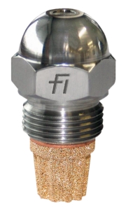
The CBM Fluidics 1.35 45° SF oil nozzle atomizes fluid at 1.35 L/h into a precise 45° spray cone. This nozzle is deceptively critical: a dirty nozzle reduces combustion efficiency by 15–20%, wastes fuel, and creates unburned hydrocarbon emissions that foul downstream equipment.
Unlike regulators and pumps, nozzles fail quickly and inexpensively—but their failure cost (lost heat output, unscheduled cleaning, emissions violations) is high.
Weekly Nozzle Visual Assessment
Nozzle performance is easiest to monitor indirectly:
- Flame color and shape: In a combustion system, a properly atomized spray creates a uniform orange flame. If your flame appears yellow, has dark streaks, or flickers, nozzle atomization is failing.
- Soot accumulation: Inspect your combustion chamber walls weekly. Excessive black soot (>2 mm thickness) indicates incomplete combustion caused by poor atomization.
- Fuel consumption drift: Compare your fuel consumption (gallons per hour) against baseline. A 10% increase with no load change points to nozzle deterioration.
- Backpressure: Measure the fluid pressure 150 mm before the nozzle inlet. If pressure is higher than baseline by >5 bar, the nozzle orifice is partially blocked.
Nozzle Cleaning and Replacement Protocol
Do not attempt to clean a nozzle tip with wire brushes or compressed air—you will enlarge the orifice and ruin atomization. Instead:
1. Shut down your system and allow the nozzle to cool to ambient temperature (minimum 10 minutes).
2. Remove the nozzle by unscrewing its connection (usually 1.5-inch SAE or NPT).
3. Soak the nozzle in commercial fuel oil or kerosene for 30 minutes to dissolve varnish and carbon deposits.
4. Flush the nozzle by passing low-pressure air (3–5 bar) through the outlet for 15 seconds.
5. Inspect the orifice using a magnifying glass. Any remaining carbon particles or visible erosion means the nozzle should be replaced, not reinstalled.
6. If the nozzle is clean, reinstall and run a 5-minute test cycle. If flame quality or fuel consumption have not returned to baseline, replace the nozzle.
Nozzle Replacement Criteria
Order a replacement nozzle when:
- Flame appearance does not improve after cleaning and flushing.
- The orifice diameter has visibly enlarged (compare against a new nozzle side-by-side).
- Soot accumulation in the combustion chamber returns within 1 week of cleaning.
- Backpressure remains >5 bar above baseline despite cleaning.
- The nozzle has operated for 2 years or more (preventive replacement reduces emergency downtime).
Section 4: Integrated System Diagnostics and Troubleshooting
The Pressure-Flow-Temperature Triangle
When a multi-fluid system performs poorly, maintenance teams instinctively focus on the failing component. In reality, most failures originate in interconnected issues. Use this diagnostic method:
Symptom: Low outlet flow
- Check regulator outlet pressure first. If pressure is correct, the pump is failing.
- If pressure is low, the regulator is drifting or relief is leaking internally.
- If pressure is high but flow is low, a blockage exists downstream (clogged nozzle, kinked hose, or restricted fitting).
- Measure bearing temperature at the pump. If it exceeds 60°C, check lubricant level and bearing condition.
- If bearing temperature is normal but outlet fluid is hot, the pump is cavitating due to low inlet pressure—check the supply line and regulator setpoint.
- If all temperatures are normal but the system feels warm to the touch, fluid viscosity may be too low for your operating pressure, causing excessive internal leakage.
- Verify nozzle cleanliness (clean if necessary).
- Measure the fluid pressure at the nozzle inlet. If it drifts >±2 bar over 10 minutes, the regulator is unstable.
- Check the pump outlet pressure. If it fluctuates, cavitation is occurring (see bearing and inlet pressure diagnostics above).
Maintenance Log Data and Trend Analysis
Maintenance teams that fail to track equipment performance over time cannot distinguish normal drift from imminent failure. Implement a simple spreadsheet or digital system to record:
- Date and time of measurement
- Component tested (regulator, pump, nozzle, hose)
- Measurement type (pressure, flow, temperature, visual condition)
- Baseline value (from commissioning documentation)
- Current value
- Percent change from baseline
- Technician name and signature
Review your logs monthly. When any measurement drifts 10–15% from baseline, schedule service before failure occurs. A 30-minute regulator recalibration costs 1/100th the price of an emergency nozzle replacement that halts production.
Spare Parts Strategy
Drawing on 35+ years of equipment distribution, 3G Electric recommends maintaining a small spare inventory proportional to your facility size:
- One complete regulator assembly (same model as your primary)
- One nozzle (same spray angle and flow rate as primary)
- Two hose segments with fittings pre-attached (same pressure rating and length as your critical runs)
- Bearing lubrication kit appropriate to your pump model
Store spares in a climate-controlled cabinet. Inspect them annually and cycle your stock every 3 years to prevent seal hardening.
Conclusion: Sustainable Maintenance Through System Integration
Maintenance & Service excellence does not emerge from reactive responses to failures. It develops when maintenance teams understand that pressure regulators, pumps, and nozzles operate as an integrated whole. A regulator that drifts 3 mbar may seem acceptable in isolation—but it creates upstream pump cavitation and downstream nozzle blockage within 100 operating hours.
Implement the protocols outlined here: monthly regulator inspection, quarterly pump flow testing, weekly nozzle assessment, and monthly trend analysis. Document everything. When a measurement approaches its failure threshold, act immediately.
Facilities that apply this disciplined approach typically extend equipment lifespan by 40–60%, reduce emergency shutdowns by 80%, and lower total cost of ownership significantly. Your maintenance team has the expertise to implement these strategies—use the detailed checklists and diagnostic pathways to support your judgment and experience.