Understanding Flame Detection Systems in Industrial Maintenance & Service
Flame detection systems represent a cornerstone of industrial safety and operational reliability across Southeast Asian manufacturing facilities. For maintenance teams operating in Singapore's regulated industrial environment, understanding flame detection architecture goes beyond basic troubleshooting—it requires systematic knowledge of component interdependencies, diagnostic methodologies, and compliance requirements.
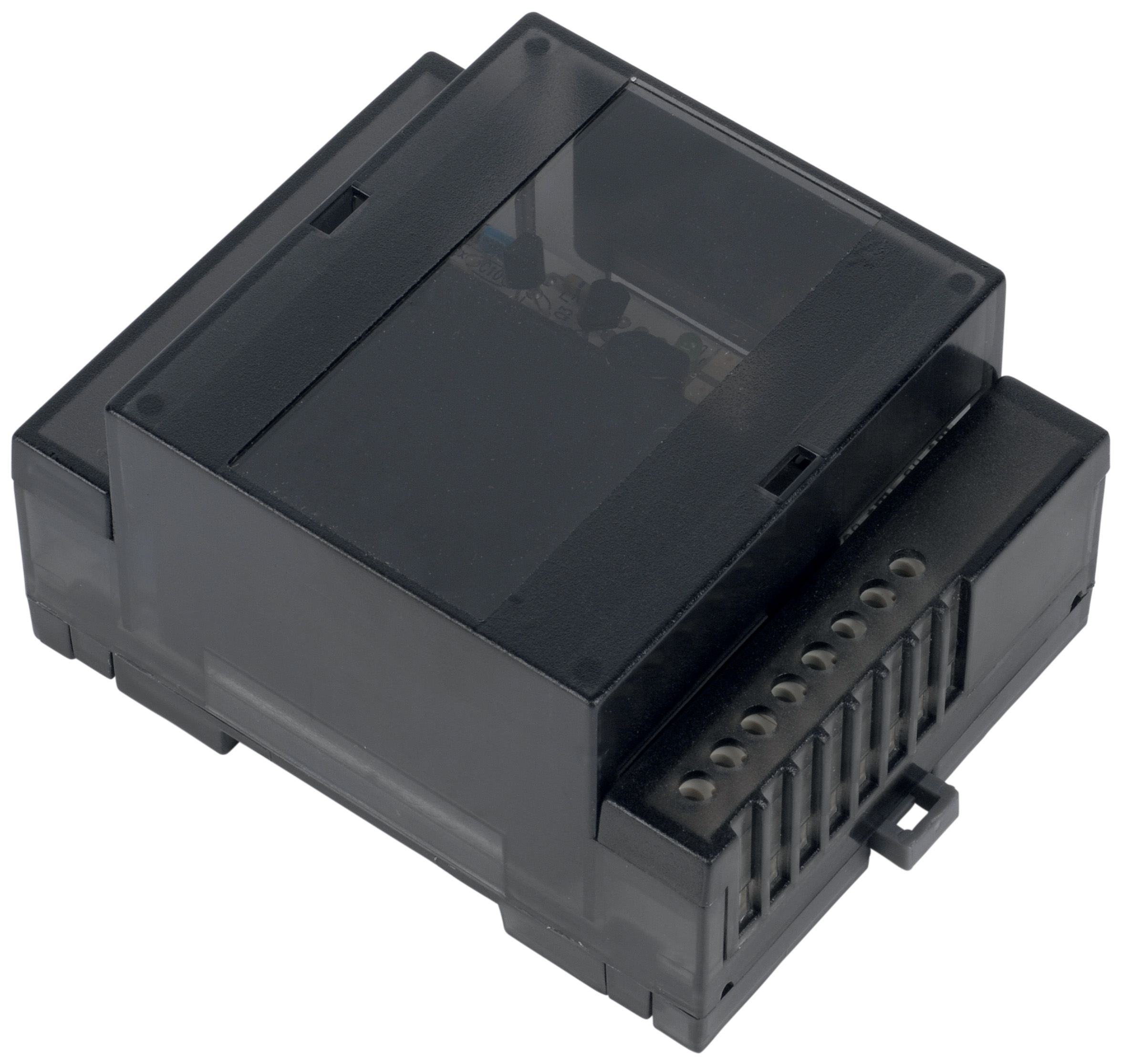
Flame relays function as the decision-making hub of combustion monitoring systems, receiving signals from UV or flame-sensing detectors and communicating system status to burner controls. The Combutech Flame relay CF1 exemplifies industrial-grade flame detection with its IP40 rating and capacity to manage up to 10 UV detectors simultaneously. With 35+ years of equipment distribution experience across Asia-Pacific industrial operations, 3G Electric recognizes that flame relay maintenance directly impacts plant safety certifications, insurance compliance, and operational continuity.
Unlike general pump or hydraulic system maintenance, flame detection system care demands specialized attention to electrical continuity, sensor responsiveness, and signal integrity. Singapore's industrial facilities—particularly those in petrochemical, food processing, and manufacturing sectors—operate under stringent safety standards where flame detection failure can trigger emergency shutdowns and regulatory investigations.
Diagnostic Protocols for Flame Relay System Health Assessment
Establishing Baseline Performance Metrics
Effective Maintenance & Service begins with establishing measurable performance baselines for your flame detection infrastructure. Maintenance teams should document initial electrical specifications including input voltage stability, relay response time, and detector signal strength before equipment enters service.
For the Combutech CF1 flame relay, baseline documentation should include:
- Input voltage stability: Record 250 VAC and 30 VDC measurements across multiple days to identify voltage fluctuation patterns that may indicate incoming power quality issues
- Relay activation lag: Measure the time interval between detector signal receipt and relay contact closure (typically 200-400 milliseconds for industrial-grade relays)
- Detector sensitivity threshold: Use calibrated test equipment to verify UV detector response at design-specified light intensities
- Contact resistance: Monitor relay contact resistance at 1A load to establish trends that indicate contact degradation
Maintenance teams should maintain detailed logs using equipment-specific forms rather than generic checklists. These logs become invaluable when investigating unexpected shutdowns or preparing documentation for Singapore's workplace safety and health audits.
Signal Path Integrity Testing
Flame detection systems consist of distinct signal paths: detector-to-relay communication, relay-to-burner control signaling, and diagnostic output circuits. Each path requires independent verification.
UV Detector Signal Verification: Combutech CF1 relays managing multiple UV detectors require methodical testing of each detector circuit independently. Maintenance teams should:
1. Isolate each detector by disconnecting its signal cable while monitoring relay status
2. Verify that relay alarm output activates when any single detector signal is interrupted
3. Document response time for each detector position on the daisy-chain configuration
4. Identify any detectors showing delayed response (>500ms) which may indicate incipient wiring or connection degradation
Output Circuit Verification: The relay's 1A @ 250 VAC and 1A @ 30 VDC output ratings mean that burner control circuits drawing near maximum rated current will operate at reduced safety margins. Test output circuits under actual load conditions rather than simulated conditions.
Environmental and Housing Integrity Inspections
The polycarbonate UL94-V0 housing on industrial flame relays provides crucial protection but requires regular assessment. Singapore's tropical humidity and industrial dust environments accelerate housing degradation.
Inspection protocol for Combutech CF1 housing:
- Examine polycarbonate surface for stress cracks, discoloration, or UV damage (indicating photodegradation)
- Verify gasket compression around electrical entry points—degraded gaskets allow moisture ingress
- Clean IP40-rated ventilation openings monthly (not just annually) to prevent dust accumulation that reduces thermal dissipation
- Document any visible moisture inside the relay enclosure; this indicates gasket failure requiring immediate replacement
- Apply protective UV-resistant coating annually to exposed polycarbonate surfaces in applications with direct sunlight exposure
Systematic Component Replacement and Upgrade Planning
Scheduled Detector Replacement Programs
UV detectors in flame relay systems operate under constant thermal and optical stress. Unlike pumps or gearboxes that degrade gradually, detectors exhibit cliff-edge failure characteristics where sensitivity suddenly drops below detection thresholds.
Maintenance teams should implement time-based detector replacement programs rather than condition-based approaches:
- Standard industrial environments: Replace UV detectors every 24 months
- High-temperature applications (burner chamber temperatures >250°C): Replace detectors every 12-18 months
- Contaminated environments (dust-heavy facilities): Replace detectors every 18 months
Scheduled replacement prevents the catastrophic scenario where detectors fail during burner operation, allowing unburned fuel accumulation before flame-out detection. This represents the primary safety risk in flame detection system failures across Singapore industrial operations.
Relay Contact and Connection Terminal Maintenance
Relay contacts corrode gradually in industrial environments, particularly in high-humidity facilities near coastal areas. Maintenance teams should:
- Inspect relay contact surfaces using magnification for green or white corrosion deposits (copper oxidation)
- Use contact cleaning spray rated for live electrical circuits when light corrosion appears
- Replace relay contact cards when discoloration covers >20% of contact surface area, even if relay remains functional
- Verify all terminal connections monthly using a torque screwdriver set to manufacturer-specified terminal torque (typically 0.5-0.8 Nm for industrial relays)
Loose terminal connections represent the #1 cause of intermittent flame detection failures in 3G Electric's 35+ years of equipment support across Asia-Pacific operations. A single loose connection can cause nuisance shutdowns affecting production schedules while masking the true root cause.
Planned Upgrades for System Expansion
As Singapore manufacturing facilities scale operations or migrate to more complex burner systems, flame detection capacity often becomes the limiting factor. The Combutech CF1 supports up to 10 UV detector inputs, but maintenance teams should understand the power budget implications of operating near maximum capacity.
When planning facility expansion:
- Verify that burner control systems can handle increased flame detection output frequency (systems with 6+ detectors generate significantly more signal traffic)
- Confirm that wiring gauge from detectors to relay remains adequate as run lengths increase
- Document relay mounting location and verify that adding detectors doesn't increase heat load beyond the relay's thermal dissipation capacity
Working with 3G Electric's supplier network allows maintenance teams to evaluate compatible relay options before expansion projects begin, preventing mid-project integration failures.
Integration with High-Pressure Industrial Systems
Flame detection systems frequently operate in integrated installations with high-pressure pumps and gearboxes. Understanding these interdependencies improves overall Maintenance & Service effectiveness.
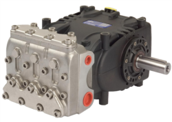
Facilities using Interpump PUMP W2035 L ATEX or Pratissoli KF30 industrial pumps in burner fuel supply systems require coordinated maintenance protocols:
- ATEX-rated components integration: ATEX-compliant pumps supplying burner fuel must coordinate with flame detection systems that manage combustion safety. Maintenance schedules should align burner-side flame detection testing with fuel supply pump inspections
- Pressure relief coordination: High-pressure pumps feeding burner fuel systems often use pilot-operated relief valves. Verify that flame detection system commissioning includes fuel pressure stabilization tests to ensure detectors operate under intended fuel delivery conditions
- Gearbox and transmission maintenance: Facilities using Interpump GEARBOX RS500 to drive fuel supply pumps should schedule flame relay diagnostics after any gearbox service that affects fuel flow characteristics
Singapore industrial maintenance teams increasingly recognize that siloed equipment maintenance creates hidden integration risks. A perfectly maintained flame relay connected to a fuel supply system with degraded pump performance may exhibit false flame-out signals due to inconsistent burner flame characteristics.
Documentation, Compliance, and Continuous Improvement
Maintenance & Service excellence requires systematic documentation that serves multiple purposes: operational troubleshooting, regulatory compliance, and continuous improvement planning.
Regulatory Compliance in Singapore: Maintenance teams must maintain detailed records demonstrating that flame detection systems meet Singapore Standards (SS) requirements and industry safety standards. Documentation should include:
- Commissioning reports from initial system installation
- Monthly inspection logs with specific measurements (not generic "OK/Not OK" checkboxes)
- Any detector replacements with date, model, and batch number
- Diagnostic test results showing relay response times and signal strengths
- Any modifications or upgrades with justification and approval documentation
- Gradual increases in relay response time (warning sign of contact degradation)
- Seasonal variation in false alarm rates (indicates environmental stress factors)
- Detector sensitivity decay patterns (helps optimize replacement timing)
This data-driven approach reduces unplanned downtime while optimizing maintenance budgets—critical considerations in Singapore's cost-competitive manufacturing environment.
Practical Troubleshooting for Common Flame Detection Issues
Maintenance teams frequently encounter recurring flame detection problems that require systematic diagnostic approaches:
Intermittent Flame-Out Signals: Before concluding relay failure, verify detector mounting angles haven't shifted and UV viewing windows remain clean. Dust accumulation on detector lenses is the #1 cause of intermittent false signals in Singapore industrial facilities.
Nuisance Alarms During Startup: Many flame relays exhibit brief signal instability during burner ignition before flame becomes established. If nuisance alarms occur consistently, verify that relay flame detection delay settings match burner ignition characteristics. Mismatched settings cause safety shutdowns during normal startup sequences.
Loss of Signal from Specific Detector: Isolate affected detector by disconnecting its connector. If relay alarm activates immediately, the detector itself has failed. If alarm doesn't activate, wiring integrity between detector and relay is compromised—check for pinched or corroded connector pins.
These troubleshooting sequences save maintenance teams countless hours of trial-and-error diagnostics while ensuring systematic root-cause identification rather than component replacement guesswork.