Understanding Integrated System Maintenance & Service
Maintenance & Service in modern industrial operations extends beyond single-component care. When you operate interconnected equipment—high-pressure pumps coupled with transmission systems, control relays, and hazardous-area components—failures in one area cascade rapidly through the entire assembly.
With over 35 years of experience as an equipment distributor, 3G Electric has observed that maintenance teams achieving the highest uptime rates treat their systems holistically rather than managing pumps, gearboxes, and controls in isolation. This integrated approach reduces diagnostic time by 40-60% and prevents secondary failures that occur when operators replace one component without addressing root causes in connected equipment.
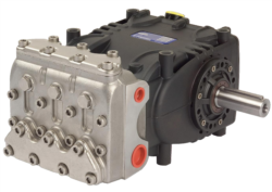
Integrated maintenance & service requires understanding how fluid pressure, mechanical load, electrical signaling, and environmental conditions interact across your equipment portfolio. A failing seal in a Pratissoli SN7045 L pump may initially appear as a pressure loss problem, but could stem from improper gearbox alignment or contaminated hydraulic fluid from the transmission system.
Diagnostic Protocols for Multi-Component Systems
Establishing Baseline Performance Data
Before implementing diagnostic routines, establish documented baseline readings for each integrated system:
Pressure and Flow Assessment
- Record pump discharge pressure under full load (critical for systems using Pratissoli KF30 pumps or Interpump W2035 L ATEX)
- Document flow rates at 50%, 75%, and 100% operational capacity
- Compare readings against manufacturer specifications—deviations exceeding 5% indicate internal wear
- For ATEX-rated equipment, verify pressure stability without fluctuation spikes that could trigger false safety shutdowns
- Inspect coupling alignment between pump and Interpump GEARBOX RS500 using dial indicators (tolerance ±0.05mm)
- Measure vibration at pump inlet, discharge, and transmission output using portable vibration meters
- Document baseline noise signatures—changes in acoustic patterns precede catastrophic failures by 2-4 weeks
- Monitor temperature at transmission bearing housings; increases above 55°C indicate friction problems
- Establish baseline fluid viscosity, acid number, and water content through laboratory analysis quarterly
- Track particle contamination levels using ISO 4406 codes—critical for high-pressure systems exceeding 200 bar
- For systems with Combutech Flame relay CF1 or similar control components, ensure fluid electrical conductivity remains within specifications (excessive conductivity indicates water contamination)
Systematic Diagnostic Routines
Implement three-tier diagnostic protocols aligned to your operational tempo:
Daily Operator Checks (5-10 minutes)
- Visual inspection: fluid color, leakage around seals, coupling security
- Pressure gauge readings: compare to logged baseline; alert maintenance if deviation exceeds ±8%
- Noise assessment: sudden pitch changes or grinding sounds indicate imminent failures
- Temperature visual check: feel accessible housing areas (use thermal markers at 55°C, 65°C, 75°C)
- Detailed vibration analysis with trending software; establish alarm thresholds at 80% of critical values
- Fluid sampling from transmission case and pump discharge; compare particle counts to baseline
- Electrical verification of control systems: measure voltage at Combutech CF1 relay inputs (should read nominal ±2% from nameplate)
- Coupling inspection with visual magnification; mark wear patterns on shaft seals
- Pressure transducer calibration drift verification (±1% accuracy minimum)
- Full system hydraulic oil analysis through certified laboratory
- Thermographic imaging of pump casings, transmission bearings, and motor windings
- Acoustic ultrasound inspection of seals and bearing conditions
- Gearbox fluid drain and filter element inspection; document particle size distribution
- Electrical continuity testing of interlock circuits and safety relay chains
- Documentation of all findings in computerized maintenance management system (CMMS) with trend analysis
Preventive Replacement Intervals for Integrated Systems
Critical Components Requiring Scheduled Replacement
Maintenance & Service effectiveness depends on replacing components before catastrophic failure occurs. Use age-based and condition-based triggers:
Hydraulic Seals and O-rings
- Primary wear item in all high-pressure assemblies
- Replacement interval: 2,000 operating hours or 24 months, whichever occurs first
- For ATEX-rated pumps like Interpump W2035 L ATEX, use only certified ATEX-compliant replacement seals
- Maintain parts inventory equivalent to 2-3 seal replacement kits per operational unit
- Complete fluid replacement: 6,000 operating hours or annually
- Primary filter replacement: 2,000 hours or every 6 months
- Secondary (offline) filter during condition-based intervals when particle count exceeds ISO 4406 code 18/16/13
- For systems using Interpump GEARBOX RS500, verify fluid meets ISO VG 46 specification with appropriate anti-wear additives
- Swashplate assemblies and valve plates: 5,000-8,000 operating hours depending on pressure cycling frequency
- Internal pistons and cylinder blocks: 10,000+ operating hours (replace only if pressure drops >15% from baseline)
- For Pratissoli SN7045 L and Pratissoli KF30, monitor displacement loss monthly; replacement triggered at >10% loss
- Pressure transducers: annual verification against certified calibration standard
- Combutech Flame relay CF1 detector modules: replace every 3 years or per manufacturer end-of-life date
- Solenoid valve coils: replacement every 2,000 operating hours in hazardous environments
Triggering Early Replacement
Condition-based monitoring may indicate replacement before scheduled intervals:
- Pressure performance loss exceeding 10% from baseline within 3 months suggests internal component wear
- Vibration increases >1.5 times baseline indicate bearing damage or coupling misalignment requiring gearbox inspection
- Fluid particle count rising >4 ISO codes from baseline in 30 days indicates accelerated internal wear
- Temperature stability loss (±10°C swings during constant-load operation) suggests seal degradation
- Electrical relay chatter or dropout events signal Combutech CF1 detector malfunction
Maintenance & Service Documentation and Knowledge Management
Creating Maintainability Records
Organizational knowledge about your specific equipment is as critical as the components themselves. Maintain detailed equipment histories:
Required Documentation Elements
- Equipment nameplate data: manufacturer, model, serial number, pressure rating, flow rating
- Installation diagrams showing pump-to-gearbox coupling, pressure line routing, and electrical connections
- Baseline performance data sheet (initial commissioning readings)
- Component replacement log with dates, parts replaced, and performance impact
- Failure analysis reports for any unplanned shutdowns (root cause, corrective actions, secondary failures observed)
- Spare parts inventory with part numbers, quantities on hand, and reorder levels
- Operator and maintenance training records
- Use CMMS software to centralize all historical data, making it searchable across your global operations
- Photograph equipment assemblies from multiple angles during installation for future reference technicians
- Create video training content showing correct disassembly, seal replacement, and fluid sampling procedures
- Establish alarm thresholds in condition monitoring systems that automatically escalate when readings approach critical values
Knowledge Transfer for Global Operations
Maintenance teams across different global locations often develop equipment-specific expertise independently. Prevent knowledge silos:
- Conduct quarterly cross-site maintenance conferences (in-person or virtual) where teams present failure cases and solutions
- Maintain shared repositories of technical drawings, maintenance procedures, and troubleshooting guides accessible to all locations
- Rotate experienced maintenance technicians between global facilities to transfer hands-on knowledge
- Document "lessons learned" from equipment failures and distribute to all sites operating similar systems
Troubleshooting Integration Points: Common Failure Scenarios
Scenario 1: Pump Pressure Loss Without Seal Leakage
Symptom: Pratissoli SN7045 L pump system pressure drops 12% over 6 weeks; no external leakage observed.
Diagnostic approach:
1. Measure flow rate at full displacement—if normal, internal leakage confirmed
2. Inspect transmission fluid from Interpump GEARBOX RS500 case; particle count elevation indicates pump internal wear
3. Check gearbox alignment; misalignment causes shaft deflection, reducing pump case pressure integrity
4. Verify electrical signals to any proportional control valves—electrical drift can cause internal spooling errors
Resolution: Likely internal valve plate wear; schedule pump rebuild during next planned downtime. Interim: reduce system pressure 8% to extend component life.
Scenario 2: Control Relay Nuisance Trips
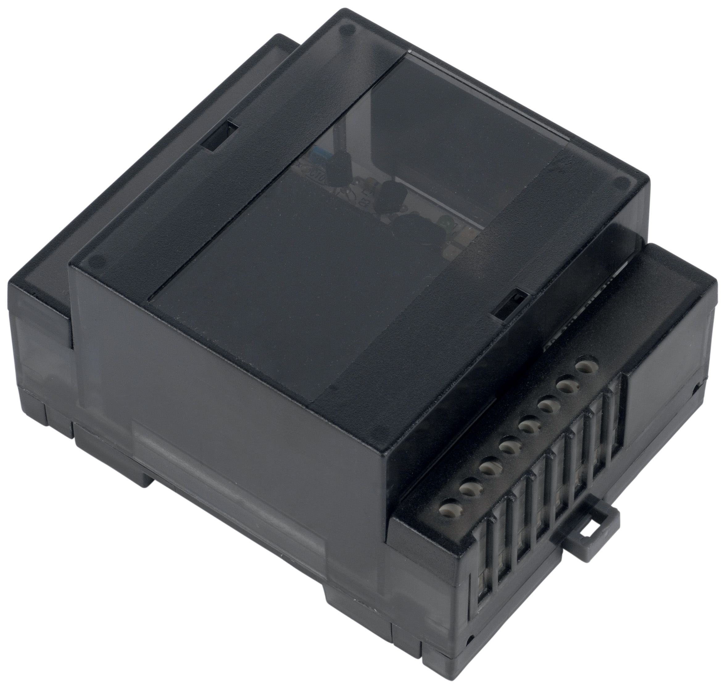
Symptom: Combutech Flame relay CF1 trips safety shutdown despite stable system operation.
Diagnostic approach:
1. Verify detector module electrical connections; loose crimps cause intermittent signal loss
2. Measure voltage at relay input terminals; fluctuation >±3% from nominal suggests power supply instability
3. Check for UV interference sources (arc welding nearby, arc lights) that confuse flame detection circuits
4. Inspect detector window for oil mist contamination reducing UV signal transmission
Resolution: Clean detector optics; verify power supply regulation; if trips continue, replace relay module (typically 3-year service life).
Scenario 3: Excessive Temperature at Transmission Output
Symptom: Interpump GEARBOX RS500 bearing housing reaches 72°C at 40% load (baseline was 52°C).
Diagnostic approach:
1. Measure gearbox bearing endplay using dial indicator; excessive play indicates bearing degradation
2. Check transmission fluid level; even 10% underfill reduces lubrication film
3. Verify input pump pressure; over-pressurization increases mechanical losses
4. Inspect for coupling runout >0.10mm indicating shaft deflection
Resolution: Top-up fluid to proper level; if temperature persists, bearing failure imminent—schedule gearbox bearing replacement within 2 weeks.
Conclusion: Building Sustainable Maintenance & Service Excellence
Maintenance & Service in globally distributed operations succeeds when teams move from reactive response to predictive management. By implementing integrated diagnostics across pumps, transmissions, controls, and hazardous-area components, you transform maintenance from a cost center into a competitive advantage.
3G Electric's 35+ years as a global equipment distributor has shown us that organizations maintaining detailed condition data, establishing clear replacement intervals, and fostering knowledge sharing across locations achieve 60-70% reduction in unplanned downtime while extending component service life by 25-40%.
Start by selecting your most critical equipment assembly (likely a high-pressure pump like Pratissoli KF30 coupled with Interpump GEARBOX RS500) and implement comprehensive baseline documentation and weekly diagnostics. Use that success case to justify expanding the program to additional systems across your global operations.