Understanding Flame Detection Systems in Southeast Asian HVAC Operations
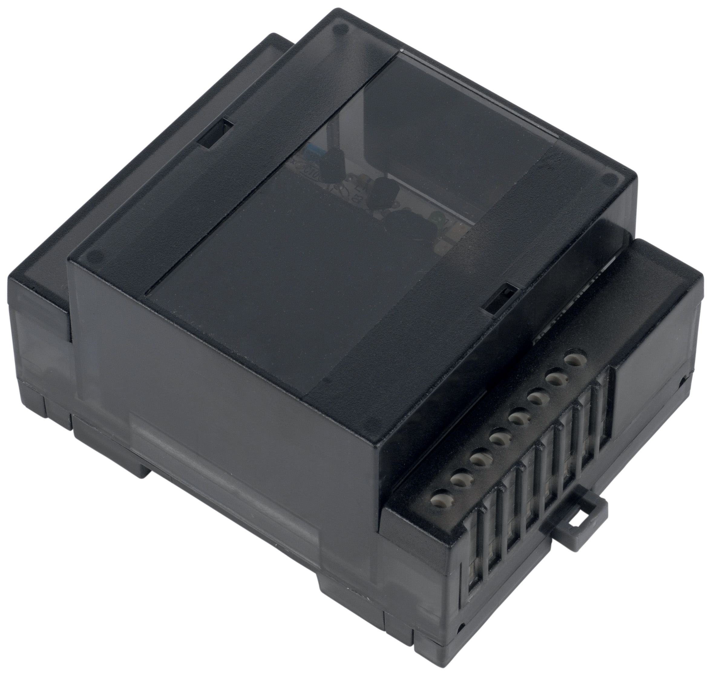
Flame detection modules are critical safety components in commercial HVAC and heating systems throughout Southeast Asia. The Combutech Flame relay CF1 represents the type of advanced detection equipment that HVAC contractors must maintain with precision. With its 1 A @ 250 VAC and 1 A @ 30 VDC ratings, this module coordinates combustion safety across complex industrial heating networks.
Southeast Asia presents unique maintenance challenges. The region's tropical climate—characterized by high humidity (70-90%), salt-laden air in coastal zones, and temperature fluctuations—accelerates corrosion and moisture intrusion in electrical components. Unlike temperate climates where flame relays can operate for extended periods with minimal intervention, Southeast Asian installations require proactive maintenance schedules that account for environmental stressors.
3G Electric has distributed industrial equipment across Southeast Asia for over 35 years, and we've observed that flame detection failures are rarely catastrophic; they're typically preventable through systematic monitoring. Most combustion safety incidents stem not from component defects but from neglected maintenance protocols—corroded detector terminals, fouled UV sensors, and uncalibrated relay thresholds.
Environmental Protection and Humidity Management
The Combutech Flame relay CF1's IP40 protection rating provides adequate defense against direct splashing and dust ingress, but it does not guarantee immunity to condensation-driven corrosion in high-humidity environments. HVAC contractors in Thailand, Vietnam, Malaysia, and Indonesia must implement additional protective measures beyond the module's standard enclosure.
Installation and Enclosure Strategy:
- Install flame relay modules in ventilated equipment cabinets with desiccant breathers to manage internal humidity
- Position modules away from direct exposure to outdoor air intakes; heat exchanger proximity can introduce moisture-laden air
- Apply conformal coating (acrylic or silicone-based, UL-approved) to PCB surfaces and connector terminals to prevent salt-spray corrosion
- Use stainless steel fasteners (316 grade in coastal applications) rather than galvanized hardware
The Combutech CF1 supports up to 10 UV detectors on line. These detectors—typically quartz-window sensors—degrade rapidly in humid climates. UV window fouling occurs from:
- Salt aerosol accumulation (especially in coastal industrial zones)
- Oil mist condensation from nearby equipment
- Biological growth (mold and algae) on detector windows in poorly ventilated burner chambers
Implement a 3-month detector inspection cycle (versus the 12-month interval recommended for temperate regions). Clean quartz windows with isopropyl alcohol and lint-free cloths; do not use abrasive materials that scratch the optical surface. Replace detectors that show optical degradation—reduced UV transmission directly increases false-flame detection risk.
Combustion Diagnostic Testing and Relay Calibration
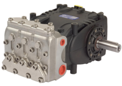
Flame detection system maintenance extends beyond hardware protection; it requires systematic combustion diagnostics tied to pump and burner performance. The Pratissoli KF30 pump (106 L/min at 200 bar, 40 kW) and Pratissoli SN7045 L pump (45 L/min at 210 bar, 18.4 kW) often operate in conjunction with flame-monitored heating systems, and fuel delivery anomalies cascade into flame detection failures.
Monthly Relay Testing Protocol:
1. Voltage Supply Verification: Confirm 250 VAC (or 30 VDC if DC-operated) at relay input terminals using a true-RMS multimeter. Voltage fluctuations >10% indicate transformer or supply-line issues that compromise relay sensitivity.
2. Detector Current Monitoring: With all UV detectors energized and burner OFF, measure detector circuit current (typically 5-15 mA per detector). Current below specification suggests detector failure or open circuit conditions.
3. Flame Signal Simulation: Use a calibrated test lamp (same spectral range as natural flame) to verify relay trip response. Record the signal intensity (lux) at which the relay engages; deviation >15% from baseline indicates optical degradation or relay drift.
4. Load Circuit Testing: Apply a controlled flame signal and verify relay switch closure under both 250 VAC and 30 VDC load conditions simultaneously if your system operates dual-voltage circuits.
Quarterly Deep Diagnostics:
- Inspect all detector mounting points for vibration looseness (use a torque wrench to verify fastener preload—typically 2-3 Nm for M6 fasteners)
- Test relay reset timing; the CF1 should return to standby state within 2 seconds of flame loss
- Measure insulation resistance between relay terminals and ground using a 500 VDC megohm meter; resistance should exceed 10 MΩ (below 1 MΩ indicates moisture intrusion)
Integration with Pump Systems and Pressure Monitoring
Flame detection systems do not operate in isolation. HVAC contractors must recognize the interdependency between combustion safety modules and the fuel delivery systems they monitor. When an Interpump PUMP W2035 L ATEX or similar high-pressure pump operates in a hazardous area, the flame relay must coordinate with pressure monitoring to ensure fuel atomization occurs only when burner ignition is confirmed.
Synchronized System Diagnostics:
- Verify pump start sequence timing: fuel pump energization should precede burner ignition command by 1-3 seconds (adjust timing on your burner control module accordingly)
- Monitor fuel pressure upstream of the burner nozzle (typically 80-250 bar depending on nozzle type); if pressure drops below minimum specification, flame detection becomes unreliable because poor atomization mimics low-intensity flame signatures
- Conduct pressure ripple analysis on ATEX-compliant pumps operating with flame-monitored burners; ripple >10% of mean pressure indicates pump cavitation, which produces false flame signals as gas bubbles travel through the nozzle
Pump seal degradation or bearing wear increases vibration, which transmits to detector mounting structures and can trigger false-positive flame signals. When HVAC contractors perform routine pump maintenance (seal inspection, bearing replacement), simultaneously verify that vibration transmission to the burner chamber has not changed. Use a portable vibration meter (acceleration range 0-20 g) to establish baseline readings on flame relay mounting brackets.
Developing a Regional Maintenance Schedule
Generic OEM maintenance schedules do not account for Southeast Asian environmental variables. Contractors must implement a climate-adjusted protocol:
Standard Maintenance Calendar (Non-Coastal):
- Monthly: Visual inspection, voltage verification, detector current check
- Quarterly: Full relay diagnostics, detector window cleaning, UV sensor replacement assessment
- Biannually: Conformal coating reapplication, fastener inspection, complete system safety audit
- Annually: Relay factory calibration (if drifts exceed tolerance bands)
- Monthly maintenance intervals unchanged
- Quarterly diagnostics increased to bi-monthly for installations <5 km from salt water
- Biannual activities compressed to quarterly cycles
- Desiccant breather replacement increased from annual to quarterly (more frequent in monsoon seasons)
Maintain detailed logs of detector current, relay trip voltage, and insulation resistance measurements. After 3-6 months of data collection, plot trends to identify degradation trajectories. A 2% per month decrease in detector current is normal aging; >5% per month indicates accelerated fouling or UV window degradation requiring immediate intervention.
Safety Compliance and ATEX Considerations
For HVAC systems operating in Zone 1 or Zone 2 hazardous areas (common in petrochemical plants and chemical processing facilities throughout Southeast Asia), flame detection becomes part of the certified safety instrumented system (SIS). The Combutech CF1's polycarbonate UL94-V0 housing meets flammability standards, but maintenance must not compromise certification integrity.
When servicing ATEX-compliant systems:
- Do not substitute connector types; use only the exact materials specified in the equipment certificate
- Never remove or modify equipment markings that identify ATEX compliance category
- Coordinate maintenance windows with facility safety departments; shutdown and service procedures must follow hazardous area entry protocols
- Retain all service documentation for regulatory audits; regulators in Thailand, Indonesia, and Vietnam increasingly scrutinize maintenance records for compliance verification
Working with 3G Electric as your equipment distributor ensures access to authentic components and technical support from professionals experienced in Southeast Asian industrial regulations. Our supply network spans major industrial zones in Singapore, Kuala Lumpur, Bangkok, Ho Chi Minh City, and Jakarta, with local service representatives familiar with regional compliance requirements.