Understanding Measurement & Detection in Preventive Maintenance Strategy
Measurement & Detection technologies form the foundation of modern preventive maintenance programs. Rather than responding to failures reactively, maintenance teams use continuous measurement systems to monitor critical parameters and detect degradation patterns before catastrophic failure occurs.
At 3G Electric, with over 35 years of experience as a global industrial equipment distributor, we've observed that facilities implementing comprehensive measurement and detection protocols reduce unplanned downtime by 40-60%. The key difference between facilities that succeed and those that struggle often comes down to understanding what to measure, how to measure it, and when measurements indicate actionable problems.
Temperature and pressure are the two most critical parameters in industrial systems. Abnormal temperature patterns often signal bearing wear, fluid degradation, or system inefficiency. Pressure anomalies indicate blockages, seal degradation, or hydraulic system failures. When your maintenance team has reliable detection tools, you transition from calendar-based maintenance to condition-based maintenance—a shift that dramatically improves operational efficiency.
Practical Temperature Measurement: Selection and Installation
Understanding Thermometer Types for Different Applications
Not all thermometers are suitable for all applications. The choice depends on your system's operating range, response time requirements, and installation constraints.
Axial Thermometers like the CBM Axial thermometer D65 -40/+40°C L5cm with thermowell are compact instruments designed for tight spaces where space constraints limit your options. These are ideal for:
- Compact HVAC units and small refrigeration systems
- Expansion tank monitoring (critical for closed-loop heating systems)
- Confined equipment cabinets where horizontal installation is impossible
- Applications requiring quick response to rapid temperature changes
The -40/+40°C range covers most HVAC and cooling applications, while the 5cm immersion length provides adequate heat transfer from the system to the sensing element. The thermowell—a protective tube around the sensor—prevents direct contact with corrosive or high-velocity fluids, extending instrument life significantly.
Vertical Thermometers like the CBM Green vertical thermometer D80 -30/+50°C L 10cm with thermowell offer larger dial displays for better readability and a wider temperature range suitable for industrial heating systems. The 10cm immersion length makes these ideal for:
- Large-diameter pipes and tanks where accurate bulk fluid temperature is essential
- Industrial boiler systems and thermal storage applications
- Applications requiring remote visual monitoring from a distance
- Systems where the thermowell protects against high-pressure fluid impact
The D80 dial provides superior visibility in low-light maintenance environments, reducing operator error and making daily rounds more efficient.
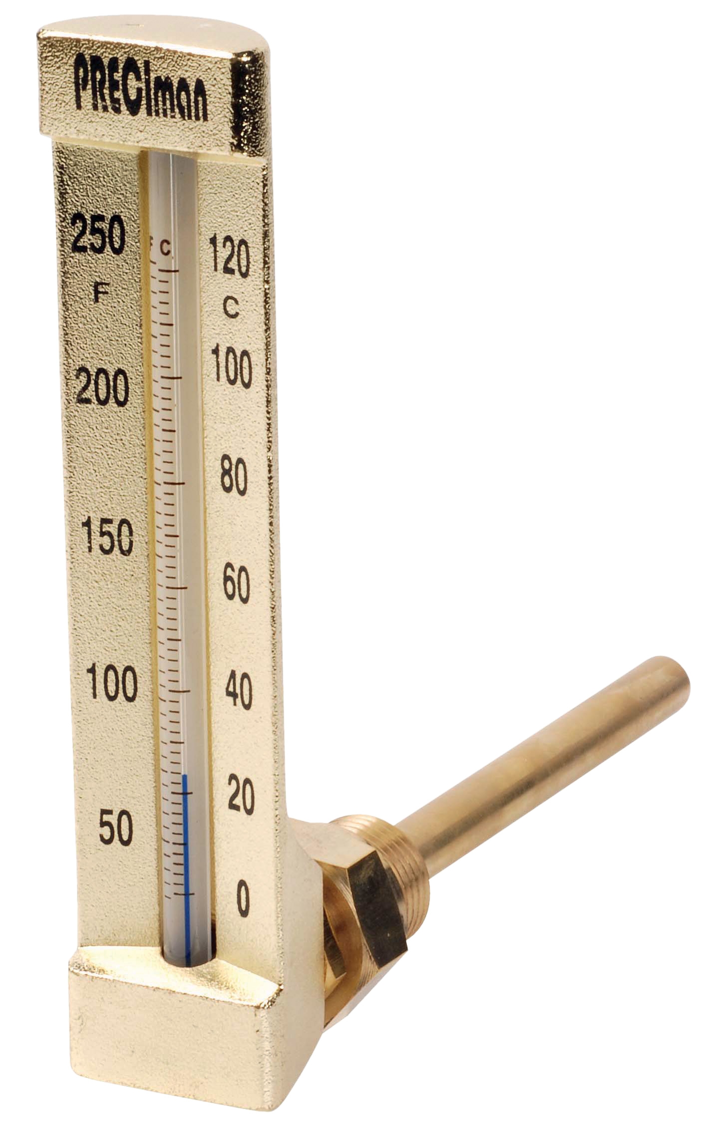
Immersion Thermometers like the CBM Industrial thermometer 0/+50°C immersion 63 right angle height 150 serve applications where the measurement point requires angular approach. The right-angle design accommodates:
- Wall-mounted or ceiling-mounted piping configurations
- Systems where a straight vertical installation would interfere with equipment access
- Applications requiring the sensing tip to penetrate perpendicular to flow direction
- Tank monitoring where the mounting flange must be oriented away from typical viewing angles
Thermometer Installation Best Practices
Proper installation determines measurement accuracy. Install temperature sensors:
1. At the point of maximum uncertainty: For outlet temperature monitoring, place thermometers immediately after the outlet, before fluid cools in pipes. For inlet monitoring, place them after circulation to ensure representative sampling.
2. In thermowells without exception: Direct immersion in flowing systems causes sensor fouling and accuracy drift. A thermowell (the protective tube) isolates the sensor from scale, corrosion, and mechanical damage while maintaining reasonable response time—typically 30-90 seconds depending on well material and fluid velocity.
3. With adequate immersion depth: The sensor element must extend fully into the fluid. Insufficient immersion causes readings to reflect pipe wall temperature rather than fluid temperature. Follow the "at least 5 diameters of the thermowell" rule for accurate measurement.
4. Away from dead zones: Avoid pockets where fluid stagnates. Install thermometers where fluid actively circulates to capture true operating conditions.
5. At standardized locations: Establish permanent mounting locations for your critical measurements. This consistency allows maintenance teams to build baseline temperature profiles and recognize degradation trends over months and years.
Detecting System Problems Through Pressure and Temperature Correlation
Building Your Diagnostic Pattern Library
Measurement & Detection becomes powerful when maintenance teams recognize patterns. A single temperature or pressure reading provides limited insight; trends provide diagnostic power.
Expansion Tank Degradation Pattern: When monitoring closed-loop heating systems with CBM Expansion tank inflator battery 2000 mAH, you're checking system charging and detecting failed bladders. A system that:
- Shows normal temperature under light load but abnormal temperature swings during heavy load
- Loses pressure rapidly between maintenance cycles
- Demonstrates temperature oscillation in the ±3°C range when setpoint is stable
...typically indicates an internal bladder failure in the expansion tank. The bladder normally separates air (which compresses) from water (which doesn't). When the bladder ruptures, water enters the air side, causing pressure regulation failures and temperature control problems. Early detection through pressure measurement and tank charging procedures prevents catastrophic failures.
Bearing Wear Detection: Temperature measurement excels at detecting bearing degradation. Compare temperatures across multiple measurement points:
- Monitor bearing housing temperature (inlet side of the bearing)
- Monitor outlet temperature after the bearing
- The temperature differential tells the story: healthy bearings typically show 2-4°C rise across the bearing area
- Worn bearings show 8-15°C rise or higher
- A sudden jump of 5°C or more between maintenance cycles signals imminent failure
- Systems running 10°C hotter than design specifications indicate fluid oxidation or filter blockage
- Inconsistent temperature across multiple measurement points suggests uneven fluid circulation or internal deposits
- Rapid temperature rise during startup (first 30 minutes) that doesn't stabilize suggests viscosity breakdown
When you detect these patterns early through systematic measurement, you schedule oil changes before deposits form, preventing costly system damage.
Electrical Measurement for System Diagnostics
Multimeter Functions for Maintenance Diagnostics
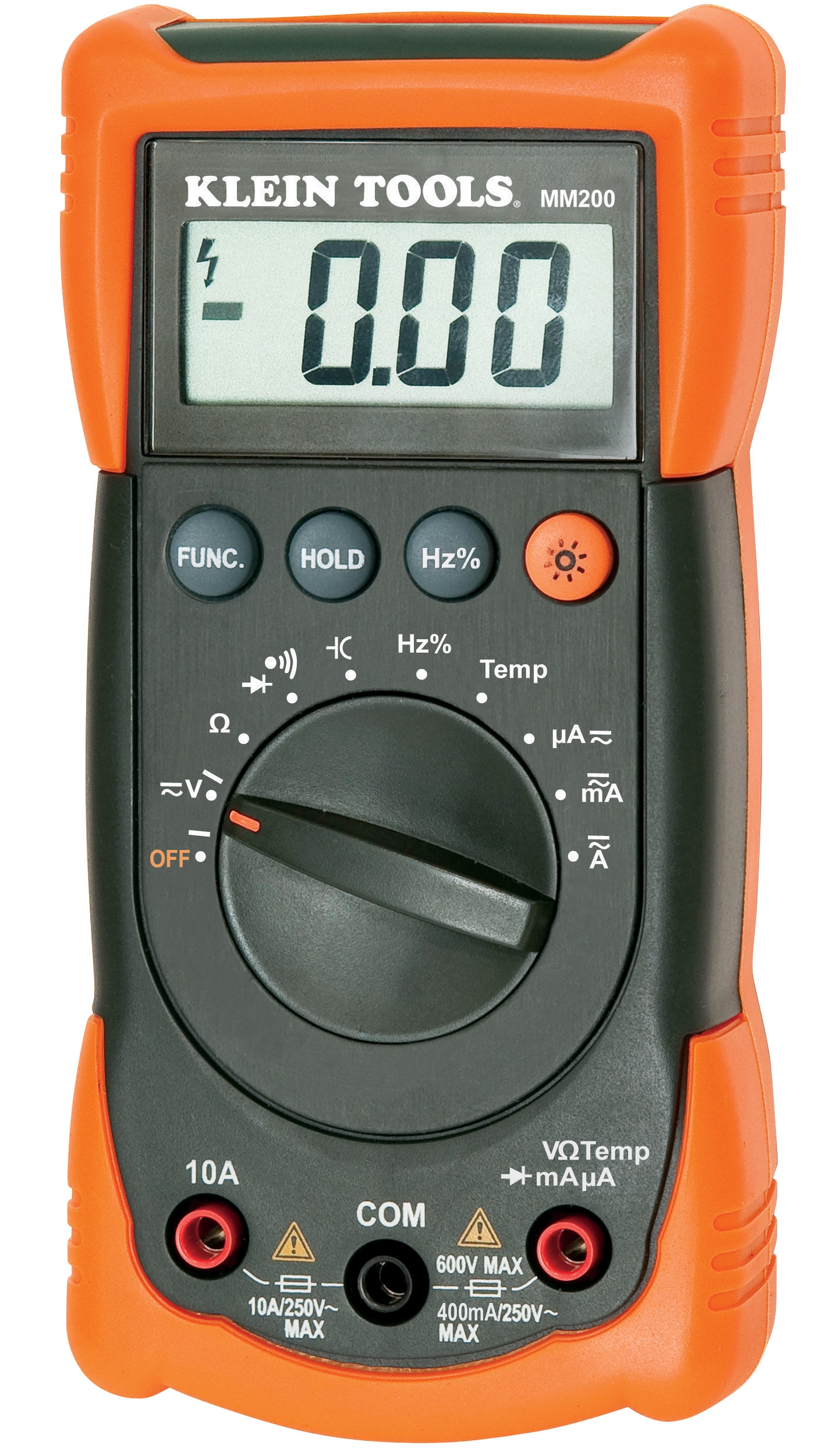
The CBM Automatic multimeter MM420 extends your diagnostic capability beyond temperature and pressure into electrical system health. Modern multimeters provide:
AC Voltage Testing: Verify that control systems and sensors receive proper power supply. Low voltage (below 85% of rated) causes sensor drift, control valve malfunction, and unreliable operation. A quick voltage check identifies power supply problems immediately.
Resistance Measurement: Test sensor continuity and heating element integrity. An open circuit (infinite resistance) in a circulation pump heating element indicates imminent failure. Resistance trending—measuring the same circuit weekly—reveals degradation: a heating element showing increasing resistance as it ages indicates carbon buildup or wire corrosion approaching failure point.
Current Draw Measurement: Compare actual current against design specifications. A pump drawing 20% more current than nameplate indicates:
- Increased viscosity (oil degradation or cold startup)
- Bearing friction increase (wear, contamination, or alignment issues)
- Impeller blockage or wear
Current draw trending provides the earliest warning of developing mechanical problems—often 2-4 weeks before temperature or pressure parameters show significant change.
Integrating Electrical and Fluid Measurements
The most effective maintenance programs correlate electrical, temperature, and pressure measurements:
- Rising amperage + rising temperature + stable pressure = mechanical friction increase (bearing wear, misalignment)
- Rising amperage + rising temperature + falling pressure = internal leakage (seal degradation, impeller wear)
- Stable amperage + rising temperature + falling pressure = external leakage or filter blockage
- Rising amperage + stable temperature + rising pressure = control valve stiction or blockage
Each pattern points to specific maintenance actions. A team armed with this diagnostic capability deploys maintenance resources precisely where needed rather than guessing.
Establishing Your Measurement & Detection Program
Creating Measurement Specifications
Begin by identifying your critical parameters:
1. List every operating system: HVAC, cooling loops, heating systems, compressed air, hydraulics, etc.
2. Identify failure modes: What typically fails? Bearings? Seals? Controls? Filters?
3. Determine critical parameters for each failure mode: Bearing wear shows in temperature and current draw. Seal degradation shows in pressure and fluid analysis. Filter blockage shows in pressure differential and system temperature.
4. Establish baseline measurements: Before implementing a measurement program, establish baseline readings under normal operation. These baselines (your system's "normal") become the reference for detecting abnormal conditions.
5. Define measurement frequency: Critical parameters like expansion tank pressure require weekly or biweekly checks. Less critical parameters might be monthly. Document your schedule.
Training Maintenance Teams
Measurement accuracy depends on proper technique:
- Standardize measurement locations: Use permanent marker or labels to mark exactly where thermometers should be placed
- Record baseline conditions: Ambient temperature, system load, operating duration at time of measurement
- Train visual inspection of instruments: Ensure team members understand dial thermometer reading (parallax error is common), digital multimeter display interpretation, and pressure gauge accuracy
- Document all readings: Spreadsheets or maintenance management software create the trend data that drives predictive insights
With 35+ years of experience supporting maintenance teams globally, 3G Electric has observed that the highest-performing teams treat measurement consistency as seriously as measurement accuracy. A precisely calibrated thermometer read incorrectly provides worse information than a slightly less accurate thermometer read consistently and correctly.
Conclusion: Measurement & Detection as Strategic Asset
Measurement & Detection systems transform maintenance from reactive firefighting to strategic asset management. By implementing systematic temperature, pressure, and electrical measurement protocols, your maintenance team shifts from responding to failures to predicting and preventing them.
The tools—thermometers, multimeters, and pressure devices—are straightforward. The power emerges from consistent application, trend analysis, and pattern recognition. A maintenance team equipped with reliable thermometers, multimeters, and pressure monitoring tools, combined with proper training and systematic data collection, achieves measurable improvements in equipment reliability, reduced downtime, and extended asset life.
As your industrial equipment partner for over 35 years, 3G Electric supports your measurement and detection strategy with quality instruments, technical expertise, and supply chain reliability across global markets.