Understanding Maintenance & Service Through Pump Specification Comparison
Maintenance & Service excellence begins before equipment failure occurs—it starts with selecting components that match your operational demands. For plant managers, understanding the relationship between pump flow rates, pressure ratings, and power consumption is essential for building reliable maintenance schedules and predicting component lifecycle.
At 3G Electric, with over 35 years of experience distributing industrial equipment globally, we've observed that most unplanned downtime stems not from component defects, but from specification mismatches. A pump specified for peak demand but running at 40% capacity operates inefficiently, generates excess heat, and requires more frequent maintenance interventions. Conversely, undersized equipment leads to cavitation, pressure spikes, and catastrophic failure.
This comparison examines how to evaluate pump specifications—flow rate, pressure, and power input—to build preventive maintenance strategies that extend equipment life and reduce total cost of ownership.
Section 1: Flow Rate Requirements and Maintenance Implications
Understanding Your Process Baseline
Flow rate, measured in liters per minute (L/min), directly impacts how often your pump operates and therefore how much thermal and mechanical stress it experiences. This stress determines maintenance intervals.
The Interpump PUMP E1D1808 L delivers 8 L/min at 180 bar—ideal for precision applications requiring stable, consistent flow with minimal pulsation. At 2800 rpm with 2.72 kW input, this compact gear pump operates in the low-to-mid flow category. Equipment operating at this scale experiences less internal wear per cycle, enabling longer intervals between seal replacements and bearing inspections.
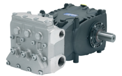
For medium-scale industrial operations, the Pratissoli KF30 provides 106 L/min at 200 bar with 40 kW input. This 13-fold increase in flow capacity means:
- Higher volumetric displacement per revolution
- Greater thermal load that requires active cooling in Maintenance & Service planning
- More frequent filter changes due to increased fluid circulation
- Shorter bearing repack intervals (typically 2,000–3,000 operating hours vs. 5,000+ for compact pumps)
The Pratissoli MW40 escalates this further to 211 L/min at 210 bar with 85 kW power input. At this scale, Maintenance & Service protocols must include:
- Weekly fluid condition monitoring (particle count, viscosity, water content)
- Quarterly thermography inspections to detect bearing degradation early
- Scheduled seal replacement every 1,500–2,000 hours
- Monthly pressure and flow trend analysis
When evaluating Maintenance & Service intervals, map your actual process flow against pump capacity. If your system requires 80 L/min average demand, selecting the KF30 (106 L/min) runs it at 75% capacity—optimal zone. Selecting the MW40 (211 L/min) runs it at only 38% capacity, creating inefficiency that generates excess heat and accelerates degradation of internal components.
Section 2: Pressure Specifications and System Stress Monitoring
How Operating Pressure Shapes Maintenance Needs
Pressure rating defines the maximum stress components endure. Higher pressure systems require:
- More robust seals (higher hardness, specialized elastomers)
- Thicker-walled hydraulic lines and fittings
- More frequent inspection of connection points for micro-leaks
- Enhanced fluid cooling capacity
The Interpump E1D1808 operates at 180 bar—a moderate pressure suitable for applications like precision coating systems or small-scale cleaning operations. At this pressure level, seal replacement intervals can extend to 3,000+ operating hours, and standard ISO 32 hydraulic fluid typically remains stable for 2,000 hours between full fluid changes.
Both Pratissoli models (KF30 and MW40) operate at 200–210 bar, entering the high-pressure category. At this range:
- Fluid oxidation accelerates, requiring more frequent sampling and analysis
- Seal material creep becomes measurable; preventive replacement intervals shorten to 1,500 hours
- Pressure relief valve performance must be verified quarterly (not annually)
- All hose assemblies should be pressure-tested and documented annually
Plant managers should establish baseline pressure readings during the first 50 operating hours. Gradual pressure decline (3–5% per 500 hours) indicates normal internal leakage. Pressure swings greater than ±10 bar suggest:
- Relief valve drift (requires recalibration)
- Pump wear (measurement for planned replacement)
- Filter blockage (immediate corrective action)
Document these trends in your Computerized Maintenance Management System (CMMS) to predict component failures 200–500 hours in advance, allowing planned maintenance during scheduled downtime rather than emergency repairs.
Section 3: Power Input and Thermal Management in Maintenance & Service Strategy
Energy Efficiency as a Maintenance Indicator
Power input (measured in kilowatts) reveals how efficiently your pump converts electrical energy to fluid energy. Power consumption trending is one of the earliest warning signs of degradation.
The Interpump E1D1808's 2.72 kW input suggests:
- Modest thermal load (minimal cooling required)
- Longer seal life in standard ambient conditions
- Lower electrical supply infrastructure requirements
- Less frequent motor bearing maintenance
As flow capacity increases, power requirements scale non-linearly:
- KF30: 40 kW (14.7× the Interpump, but flow is only 13.25×)
- MW40: 85 kW (31.3× the Interpump, but flow is only 26.4×)
This disparity reflects increased internal friction in larger pumps, which translates directly to heat generation. A facility running the MW40 at constant full load generates approximately 15–18 kW of waste heat that must be dissipated through the cooling system.
Building Thermal Management into Your Maintenance & Service Protocol
For high-flow, high-power systems, implement:
1. Baseline thermal measurement: Establish fluid temperature under rated load during commissioning (record as T-baseline)
2. Temperature trending: Log fluid temperature at startup, 30 minutes, and 2 hours into each shift
3. Alarm thresholds: Set alerts at T-baseline + 8°C; investigate root cause at +12°C; shut down at +15°C
4. Cooler performance validation: Quarterly measurement of cooler outlet temperature differential (should remain consistent; decline indicates scale buildup)
Maintenance & Service costs rise dramatically when thermal issues aren't addressed. A 5°C increase in fluid operating temperature reduces seal life by approximately 15–20%, fluid oxidation life by 25%, and bearing life by 10–15%.
Section 4: System Integration and Complementary Component Selection
Nozzles and Regulators in Your Maintenance & Service Ecosystem
Pump selection doesn't exist in isolation. Your complete system includes pressure regulation and spray delivery, which significantly impact overall reliability.
The Francel B25/37mb pressure regulator with integrated safety relief maintains stable outlet pressure (37 mbar) regardless of upstream fluctuations. In Maintenance & Service terms, this component protects downstream equipment by preventing pressure spikes that would otherwise stress seals and connectors.
The Euspray flat jet nozzle (1/4" M BSPT, 25° angle) delivers precise spray patterns, but nozzle wear occurs gradually. Maintenance & Service intervals for nozzles include:
- Visual inspection every 100 operating hours for erosion patterns
- Pressure drop testing quarterly (if ΔP increases >15%, schedule replacement)
- Flow uniformity validation semi-annually using spray test patterns
When specifying a complete system, ensure compatibility:
- Pump outlet pressure → regulator inlet pressure (must have 10–15 bar margin)
- Regulator outlet pressure → nozzle rated pressure
- Nozzle flow capacity → pump flow rate (at regulator outlet pressure)
Mismatches here create the hidden maintenance costs that erode profitability. A nozzle rated for 50 L/min installed on a 106 L/min system (with pressure regulation) creates turbulence, cavitation, and premature nozzle failure.
3G Electric's 35+ Years of Maintenance & Service Experience
Our industrial equipment distribution network has helped thousands of plant managers avoid these integration pitfalls. We provide not just components, but specification guidance that considers your facility's actual operating profile, climate conditions, and available maintenance expertise.
Building Your Maintenance & Service Decision Framework
Step 1: Document Actual Demand
Review 12 months of production logs. Calculate:
- Average flow requirement (not peak)
- Pressure needed at the point of use
- Daily operating hours
- Ambient temperature range
Select a pump with flow capacity at 65–75% of maximum demand. This zone optimizes efficiency and minimizes thermal stress.
Step 3: Plan Maintenance Intervals
Use the specifications from your selected pump to populate your CMMS:
- Seal replacement intervals (from manufacturer, adjusted for your pressure and temperature)
- Filter change intervals (based on flow rate and ambient contamination)
- Fluid analysis schedule (more frequent for high-pressure systems)
- Cooler inspection intervals (quarterly for systems >50 kW)
During the first 500 operating hours, record:
- Baseline pressure and flow
- Baseline fluid temperature
- Baseline power consumption
- Any abnormal noise or vibration characteristics
These baselines become your early-warning system for detecting degradation.
Conclusion
Maintenance & Service excellence requires matching equipment specifications to actual operational demands, not aspirational peak loads. By understanding how flow rate, pressure, and power consumption interact, plant managers can design preventive maintenance strategies that extend equipment life by 30–50% and reduce emergency downtime by 60–80%.
At 3G Electric, our global distribution network and 35+ years of industrial equipment experience position us to provide not just components, but strategic guidance on building reliable, maintainable systems. Whether you're selecting compact systems like the Interpump E1D1808 or large-capacity solutions like the Pratissoli MW40, our technical team can help optimize your specifications for maximum uptime and minimum total cost of ownership.