Understanding Predictive Maintenance & Service Fundamentals
Maintenance & Service excellence in industrial settings requires transitioning from reactive repair cycles to predictive monitoring systems. Over 35 years of experience with global industrial equipment distribution, 3G Electric has observed that maintenance teams achieving the highest uptime metrics share one critical characteristic: they implement structured condition monitoring before failures occur.
Predictive maintenance operates on three core principles: baseline establishment, continuous monitoring, and threshold-based intervention. Rather than waiting for equipment failure or adhering to rigid time-based schedules, maintenance teams using predictive approaches collect performance data across multiple parameters—pressure readings, temperature fluctuations, vibration patterns, and flow measurements—to identify degradation trends before critical failure.
The economic advantage is substantial. Organizations implementing predictive maintenance protocols report 25-30% reduction in maintenance costs, 35-45% fewer unexpected breakdowns, and 20-25% increase in equipment lifespan. For maintenance teams operating globally, these improvements translate directly to improved operational reliability across multiple facilities and regions.
Key to this approach is understanding that different equipment categories require different monitoring parameters. Pumps demand attention to vibration and pressure consistency. Expansion systems require temperature and pressure tracking. Burner systems necessitate flame detection and fuel composition analysis. Valve systems require response time and seal integrity verification.
Building Your Component Condition Monitoring Framework
Effective maintenance & service begins with documenting baseline performance for every critical component. This baseline becomes your reference point for detecting abnormalities. Maintenance teams should establish monitoring routines for three distinct component categories: pressure-critical devices, thermal-response systems, and mechanical assemblies.
Pressure System Monitoring
For equipment using pressure delivery systems, establish quarterly baseline measurements across all critical points. This includes relief valve cracking pressure, accumulator pre-charge pressure, and system operating pressure under standard load conditions. Document readings on standardized forms with equipment identification, date, technician name, ambient conditions, and operating duration.
When monitoring expansion tank systems like CBM Expansion tank inflator battery 2000 mAH, verify pre-charge pressure with nitrogen according to manufacturer specifications. Pre-charge should measure 90% of minimum system operating pressure. Any deviation exceeding 5% warrants investigation. Pressure loss over time indicates bladder deterioration or seal compromise requiring component replacement.
For nozzle systems like CBM Flat jet nozzle HP 1/4"M BSPT index 25 angle 15° and CBM Flat jet nozzle HP 1/4"M BSPT index 055 angle 15°, establish baseline spray patterns using visual inspection or pressure measurement across the spray cone. Deviations from manufacturer-specified spray angles indicate internal erosion, clogging, or structural damage. These components experience wear proportional to operating hours and fluid velocity—higher pressure systems require more frequent inspection intervals.
Thermal Response Tracking
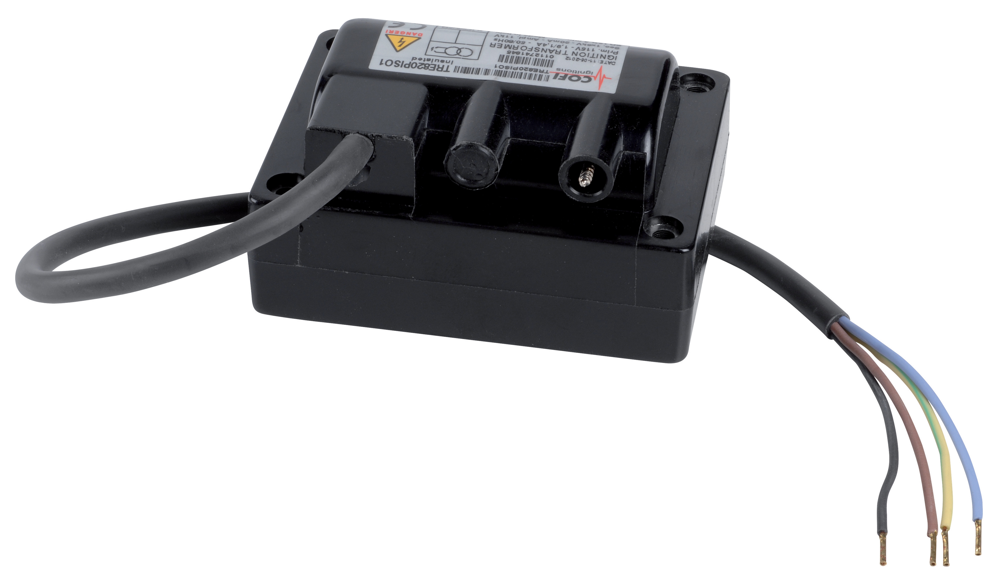
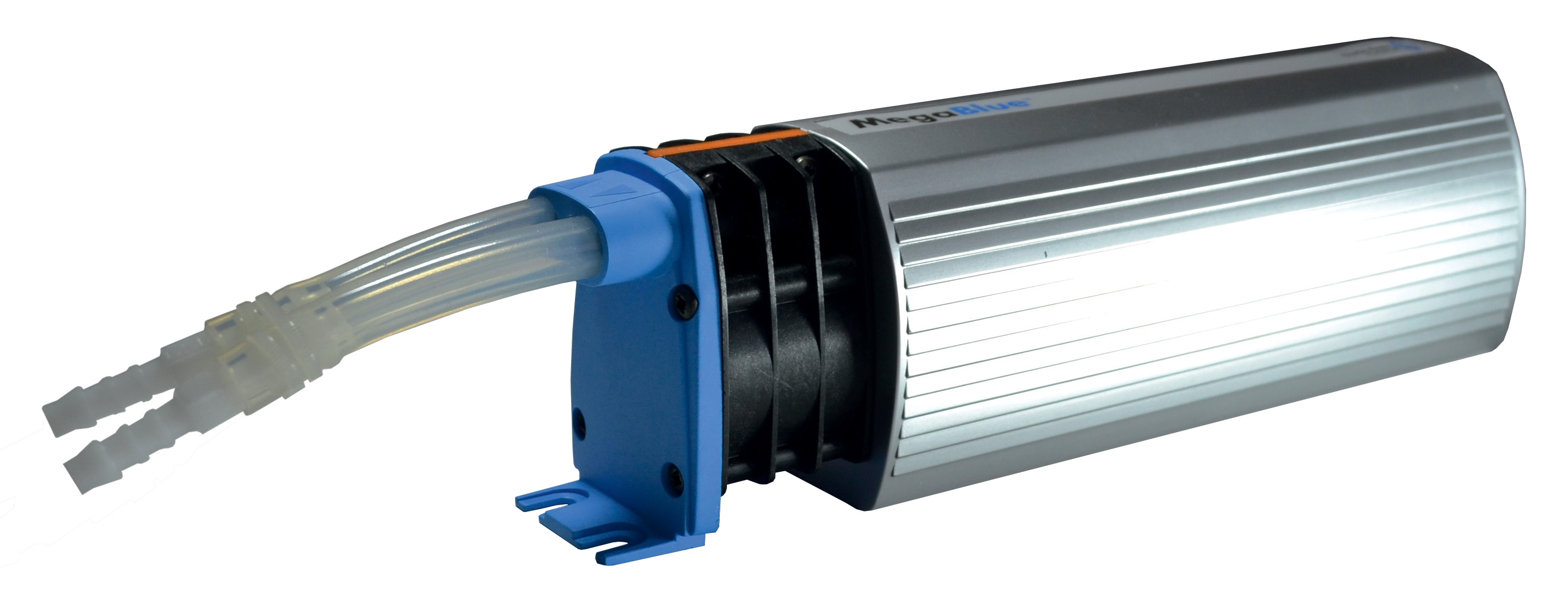
Temperature monitoring reveals degradation in thermal transfer efficiency and cooling system performance. Establish baseline temperatures at identical ambient conditions and identical equipment loads. For systems with thermal protection, like CBM Megablue reservoir alarm + shut-off X87-813, verify alarm setpoint calibration quarterly and document actual trip temperatures during controlled testing.
Temperature deviations of 10°C or greater from established baseline warrant investigation. Potential causes include reduced cooling capacity (fouled exchangers, insufficient airflow), increased internal friction (bearing degradation, seal resistance), or measurement sensor malfunction. Thermal trending over weeks reveals progressive degradation patterns that single measurements miss.
Mechanical Assembly Assessment
Vibration measurement provides early warning for bearing degradation, misalignment, and structural looseness. While professional vibration analysis requires specialized equipment, maintenance teams can establish baseline vibration "feel" by operating equipment at standard conditions and noting any changes in noise character, smoothness of operation, or tactile vibration at bearing housings.
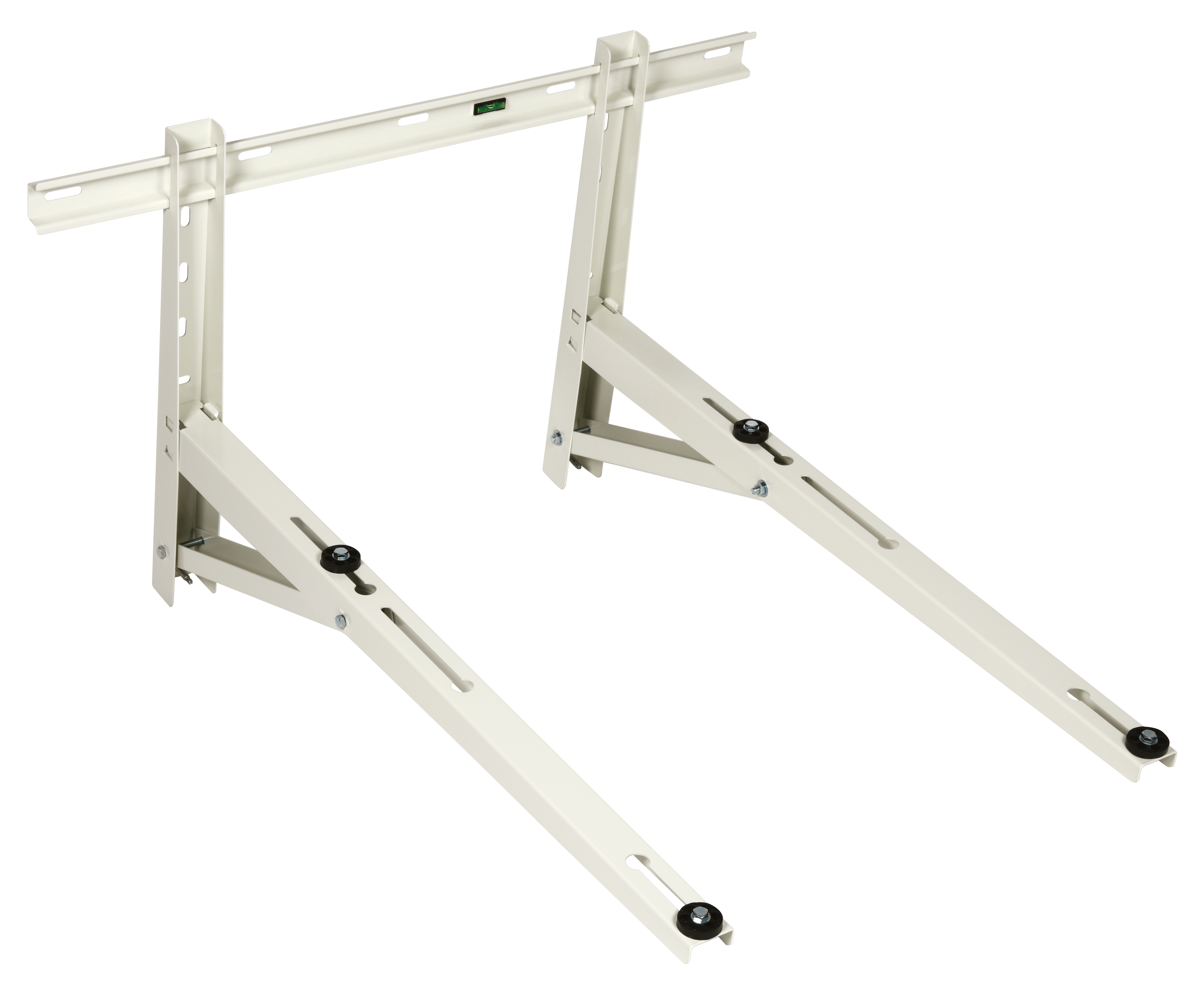
For wall-mounted installations using CBM Wall bracket 1000, verify fastener torque every six months, as vibration-induced loosening compromises safety and amplifies component damage. Additionally, inspect mounting surfaces for stress cracks radiating from fastener holes—these indicate inadequate bracket capacity or catastrophic misalignment.
Diagnostic Protocols for Systematic Troubleshooting
When maintenance teams encounter performance degradation, applying systematic diagnostic protocols prevents misdiagnosis and unnecessary component replacement. The protocol follows a logical sequence: observation, baseline comparison, root cause elimination, and targeted verification.
Phase 1: Comprehensive Observation and Documentation
Initiate diagnosis by gathering complete operational context. Document current system operating parameters—all pressures, temperatures, flow rates, cycle times—and compare against baseline conditions under identical load. Record ambient conditions as these significantly impact thermal and pressure-dependent systems. Note any operational changes: modified setpoints, new fluid batch, recent repairs, or environmental factors.
Observation should include sensory assessment: audible changes (pitch, intensity, irregularity), visual indicators (fluid leakage, discoloration, foam, crystallization), and tactile feedback (vibration changes, temperature gradients). Many early-stage failures produce subtle sensory changes before instrumentally measurable degradation occurs.
Phase 2: Systematic Baseline Comparison
Compare current measurements against established baseline and historical trends. Look beyond simple pass-fail thresholds. A pressure increase of 8% over two months followed by stabilization differs diagnostically from sudden pressure spikes. Temperature creep of 2°C weekly indicates progressive degradation; temperature fluctuations of 10°C within minutes suggest sensor or control malfunction.
Historical trending reveals patterns invisible in point-in-time measurements. Plotting pressure, temperature, or efficiency measurements chronologically helps distinguish between operational variations and degradation. Maintenance teams with six months of baseline data can typically predict component failure 4-8 weeks before catastrophic breakdown occurs.
Phase 3: Isolation and Root Cause Identification
Systematically isolate affected components by sectionalizing systems and observing behavior changes. For pressure systems, isolate sections using isolation valves and monitor pressure decay rates—rapid decay indicates active leakage; slow decay suggests relief valve bypass. For thermal systems, isolate heat sources and sinks to identify whether temperature changes originate from increased generation or reduced dissipation.
Common industrial equipment failures follow predictable patterns. Pressure relief valve drift causes system overpressure. Accumulator bladder failure produces pressure fluctuations and unusual noise. Nozzle wear generates spray pattern distortion and reduced atomization. Seal degradation produces gradual or sudden leakage. Bearing failure initially produces high-frequency vibration preceding low-frequency rumbling. Understanding failure signatures helps maintenance teams identify root causes accurately.
Phase 4: Targeted Verification Testing
Before replacing components, verify root cause through direct measurement. For suspected pressure control issues, measure relief valve cracking pressure and adjust if within specification range. For thermal concerns, verify sensor accuracy by comparing against calibrated portable instruments. For component deterioration, perform functional tests that replicate operating conditions.
For spray systems using nozzles like CBM Flat jet nozzle models, measure actual spray angle and pattern compared to specifications. For alarm systems like CBM Megablue reservoir alarm + shut-off, test setpoint calibration under controlled conditions. This verification approach prevents unnecessary replacement of functional components and focuses replacement efforts on genuinely degraded items.
Maintenance & Service Program Implementation and Global Coordination
Maintenance & Service success requires structured programs adapted to global operating conditions. 3G Electric's 35+ years supporting distributed industrial operations demonstrates that successful programs balance standardization with local adaptation.
Standardized Monitoring Protocols
Develop standardized monitoring sheets for each equipment type specifying parameters to measure, acceptable ranges, measurement frequency, and recording procedures. These sheets should be equipment-specific, reflecting the unique failure modes and critical parameters for each system type.
Monitoring frequency depends on component criticality and failure speed. Critical components like pressure relief devices and thermal protection systems warrant monthly verification. Standard pressure and temperature parameters benefit from quarterly trending. Mechanical assemblies warrant semi-annual inspection. Establish protocols accounting for seasonal variations: cooling-dependent systems need closer monitoring during warm periods; temperature-sensitive systems during cold seasons.
Global Documentation and Communication
Maintain centralized documentation of equipment specifications, baseline conditions, maintenance history, and trending data accessible to maintenance teams across locations. This approach enables rapid problem identification when equipment exhibits behavior outside established norms.
When maintenance teams identify degradation, standardized communication protocols ensure engineering teams understand severity and can coordinate parts availability. A graded reporting system helps: green status indicates all parameters within normal ranges; yellow indicates one or more parameters approaching thresholds but not yet critical; red indicates immediate failure risk.
Preventive Component Replacement Strategy
While condition monitoring prevents catastrophic failures, strategic preventive replacement optimizes costs. Components experiencing predictable wear—nozzles after specific operating hours, seals after pressure-hour accumulation, sensor calibration drift over time—benefit from scheduled replacement rather than waiting for failure.
Establish replacement intervals based on manufacturer recommendations adjusted for your operational intensity. Track replacement cost against downtime cost for each component type. Replace components on schedule when replacement cost is less than 30% of downtime cost. Extend replacement intervals when failure modes don't appear before scheduled intervals. This balance approach optimizes total cost of ownership.
Spare Parts and Supply Chain Coordination
Maintain critical spare inventory coordinated with preventive monitoring. High-failure-risk components identified through trending analysis should have spares physically located at facilities. Lower-risk components can rely on rapid-delivery supply agreements. For globally distributed operations, staging spares regionally enables rapid response while reducing redundant inventory.
Leverage experienced industrial equipment distributors like 3G Electric for supply chain optimization. With 35+ years supporting global operations, established distributors maintain strategic inventory, understand regional logistics, and can rapidly mobilize components when maintenance teams identify critical needs.
Advanced Performance Optimization Techniques
Beyond fault prevention, maintenance & service teams can optimize equipment performance through systematic efficiency assessment. Equipment operating significantly below efficiency baselines consumes excess energy and produces excessive heat, reducing component lifespan even without obvious failure symptoms.
For pressure systems, measure actual flow at known pressures and compare against nameplate specifications. Reduced flow at standard pressure indicates internal wear or blockage. For thermal systems, measure temperature differential across heating and cooling elements; reduced differential indicates fouling or insufficient flow. For mechanical systems, measure acoustic emissions and vibration acceleration—elevated levels indicate friction increases from wear or misalignment.
Implement systematic performance optimization by addressing identified inefficiencies before they produce failure. Fouled heat exchangers receive cleaning; misaligned components receive realignment; worn seals receive replacement; degraded insulators receive restoration. These proactive measures maintain equipment within optimal performance envelope, preventing the catastrophic downtime resulting from deferred maintenance.
Maintenance teams leveraging condition monitoring, systematic diagnostics, and preventive optimization achieve the reliability metrics that distinguish world-class operations. By implementing these approaches with equipment like CBM expansion tank systems, CBM pressure nozzles, and CBM alarm protection systems, maintenance teams transform from reactive failure response to predictive performance optimization.